Technical Paper|TSD-05TP
Full Support, Interior Loads, and the Missing Joint Factor: The Thickness Methods of ACI 360R-10 and Their PCA Lineage
Nigel Parkes and Robert Rodden
The Slab Designer, LLC | Published October 26, 2026 | Revised November 4, 2026
Abstract
ACI 360R-10 is the reference most often used to establish the standard of practice for industrial slab-on-ground design in the United States. It presents three thickness methods (PCA, WRI, and COE) as generally accepted, and in its chapter on curling it states that all three "give erroneous results for slab thickness where the slab is not in contact with the subgrade." This paper examines the basis of that statement and its consequences. All three methods derive from Westergaard's solutions for a slab in full contact with a uniform foundation, and two of them address only loads in the panel interior. For a 7,000 lb (31 kN) wheel on a 7 in. (180 mm) slab, Westergaard's own solutions give an edge stress about 54% higher than the interior stress, consistent with the 50% to 60% increase that led PCA to add a joint factor of up to 1.6 to its floor method in 2001 and to expand it in 2008. In PCA's 2008 metric lift truck example, the joint condition alone changes the required thickness from 180 mm (7 in.) with dowels to 235 mm (9.25 in.) at a free edge. ACI 360R-10, published in 2010, cites the 2001 PCA edition, works its PCA examples with interior charts and no joint factor, and does not tell the reader that the method's publisher had changed it to account for joints. A designer who follows the guide's procedure for an undoweled slab can therefore arrive at a thickness 2 in. or more less than PCA's current method requires, with the only warning located in a different chapter. The paper recommends that the guide reference the 2008 PCA edition with its joint factor and free-edge charts, show examples with and without load transfer, and give guidance for the finite element analysis it already describes as appropriate for jointed slabs.
Keywords: ACI 360R-10, slab thickness design, PCA method, joint factor, Westergaard, load transfer, curling, standard of care
Introduction
ACI 318 does not govern ordinary slabs-on-ground; its commentary refers designers to ACI 360. As a result, ACI 360R-10, Guide to Design of Slabs-on-Ground (1), although a guide rather than a code, is the document most often cited by designers, peer reviewers, and expert witnesses as the standard of practice for warehouse and industrial floors.
For thickness design, the guide presents three methods as "generally accepted": the Portland Cement Association (PCA) method (now published by the American Cement Association), the Wire Reinforcement Institute (WRI) method, and the U.S. Army Corps of Engineers (COE) method. Each is supported by charts and worked examples in the guide's appendices, so an engineer can follow any of them step by step to a thickness.
The same guide, in Section 14.13, states that these methods "give erroneous results for slab thickness where the slab is not in contact with the subgrade." This paper examines how both statements came to coexist, quantifies the effect on thickness for the most widely used method, and identifies the change in the method's own publication that the guide does not carry.
The Westergaard Basis
All three methods trace to Westergaard's closed-form solutions of the 1920s (2). To make the problem tractable, Westergaard idealized the slab as a plate in full contact with a bed of independent springs of uniform stiffness k, with no joints in the interior case and the load placed well away from any edge. He also solved edge and corner cases, and those solutions made clear from the start that loads at slab boundaries are more severe than interior loads.
Applying Westergaard's interior, edge, and corner solutions to a 7,000 lb (31 kN) wheel on a 4 in. (100 mm) radius contact area, on a 7 in. (180 mm) slab with E = 4,000,000 psi (27.6 GPa) and k = 100 psi/in. (27 MPa/m), gives an interior stress of about 215 psi (1.5 MPa), an edge stress of about 332 psi (2.3 MPa), and a corner stress of about 280 psi (1.9 MPa). The edge stress is 54% higher than the interior stress. These are full-support values. When an indoor slab curls upward, its edges and corners lose contact with the subgrade, and a load near a joint is carried by a cantilever rather than by the foundation, which increases the stress further and moves it to the top of the slab (Figure 1).
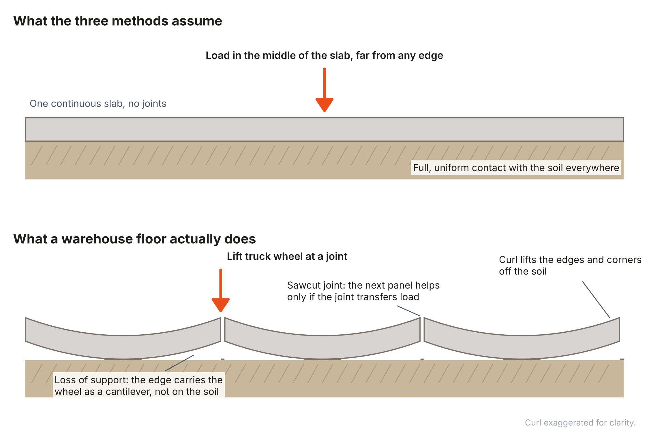
The PCA and WRI methods compute interior stress only. The COE method applies a fixed 25% reduction in edge stress to represent load transfer at every joint, regardless of whether the joint is doweled, and does not cover rack posts or distributed storage loads. The guide cites no WRI publication for the WRI method.
What the Guide Says About Its Methods
ACI 360R-10 is candid about these limitations, but it states them outside the chapter where designers select a method. Section 14.13 states: "Because the three commonly used slab thickness design methods (PCA, WRI, and COE) all are based on Westergaard's work and the assumption that slabs are always fully supported by the subgrade, they give erroneous results for slab thickness where the slab is not in contact with the subgrade." Section 7.2 notes that most of the methods "do not provide for loading at free edges and corners" and that the designer "should carefully consider such loading." Section 1.4.3 describes finite element analysis as suitable for slabs, "particularly those with discontinuities." The guide reports curling stresses of 200 to 450 psi (Section 14.1), of the same order as the load stresses a design allows, and notes that curl-induced stresses are not considered by the methods.
Every interior floor has joints, and every interior floor curls. The conditions the guide identifies as producing erroneous results are therefore not exceptional; they occur at the joints and edges of nearly every panel, where lift truck traffic crosses and rack posts are placed.
The PCA Method and the Joint Factor
The PCA method is the most widely used of the three, and its publication history shows that the joint problem was recognized and partially addressed well before ACI 360R-10 (Figure 2).
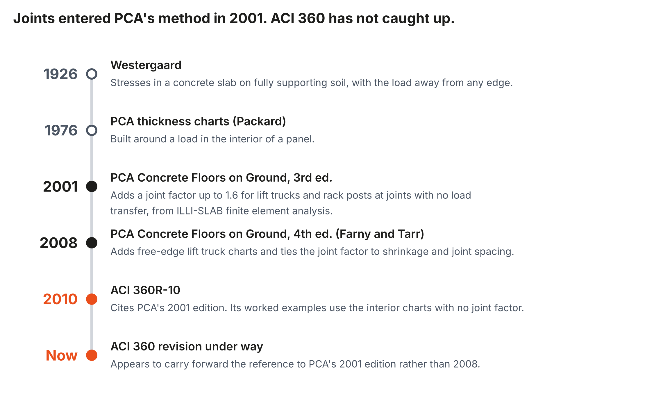
The PCA floor charts developed by Packard in 1976 (3) are built around a load in the slab interior. The first edition of Concrete Floors on Ground (7), by Spears in 1978, used those charts on the assumption that, when the slab edges at all joints have adequate load transfer, a panel acts as part of a continuous slab. For free edges without load transfer it called for thickening the slab 50% where lift trucks cross, as at a doorway isolation joint, and for rack legs near joints it asked designers to choose safety factors that allow for the higher edge stresses. The second edition (8), by Spears and Panarese in 1983, kept that basis but reduced the free-edge thickening to 25%, tapered over 5 ft, noting that dowels "may be preferable for load transfer." The third edition of Concrete Floors on Ground (4), published in 2001, introduced a joint factor of up to 1.6 for lift trucks and rack posts at joints with no load transfer (1.3 for lift trucks where joints are closely spaced and aggregate interlock is good), based on ILLI-SLAB finite element analysis showing edge stresses 50% to 60% higher than interior stresses. The fourth edition (5), by Farny and Tarr in 2008, added free-edge charts for lift trucks and related the joint factor to shrinkage and joint spacing. It explains the reason directly: the original charts give stresses "at the interior of a slab, assuming that the load is applied at some distance from any joint," and "when the load is applied at the joints the resulting stress can be significantly higher." It directs the designer to apply a joint factor of 1.0 where dowels are properly installed and full load transfer is assured, rising to 1.6 "when free edge loading is anticipated and no load transfer is present."
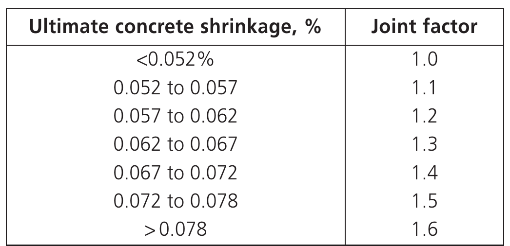
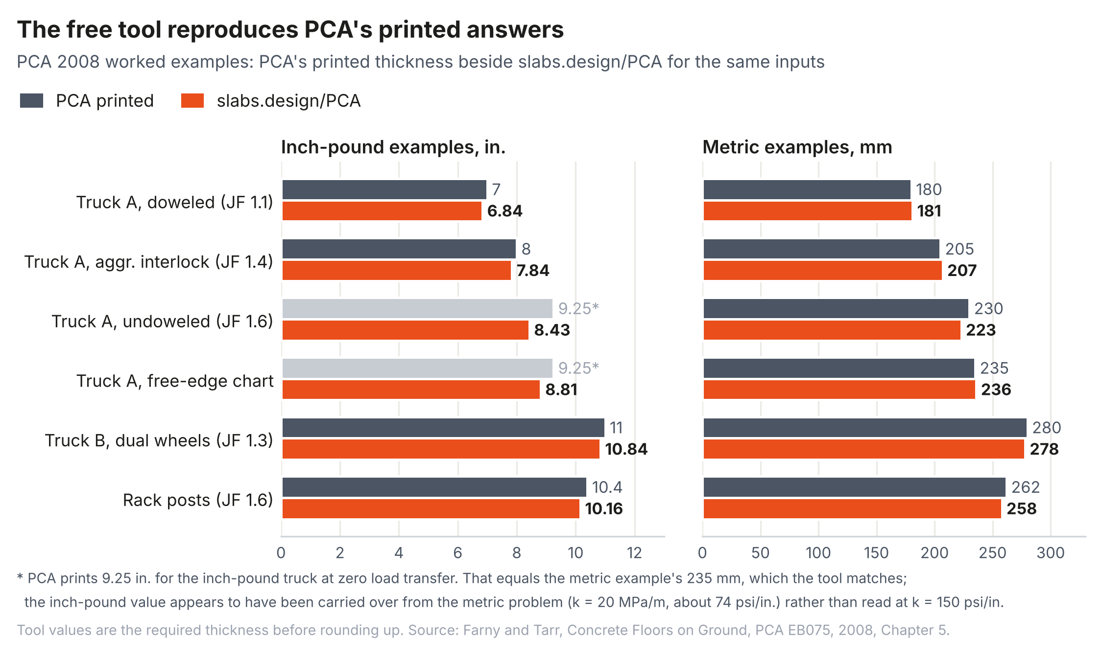
The effect on thickness is substantial. In PCA's 2008 metric lift truck example, with the same truck, concrete, and subgrade in every case, the required thickness is 180 mm (7 in.) with doweled joints (joint factor 1.1), 205 mm (8 in.) with aggregate interlock in low-shrinkage concrete at short joint spacing (1.4), and 235 mm (9.25 in.) at a free edge (1.6). The joint condition is worth more than 50 mm (2 in.) of concrete. The inch-pound version of the same example prints 9.25 in. (230 mm) for the free edge, which matches the metric 235 mm rather than an independent inch-pound solution and appears to have been carried over from the metric problem; the metric example is used here for that reason.
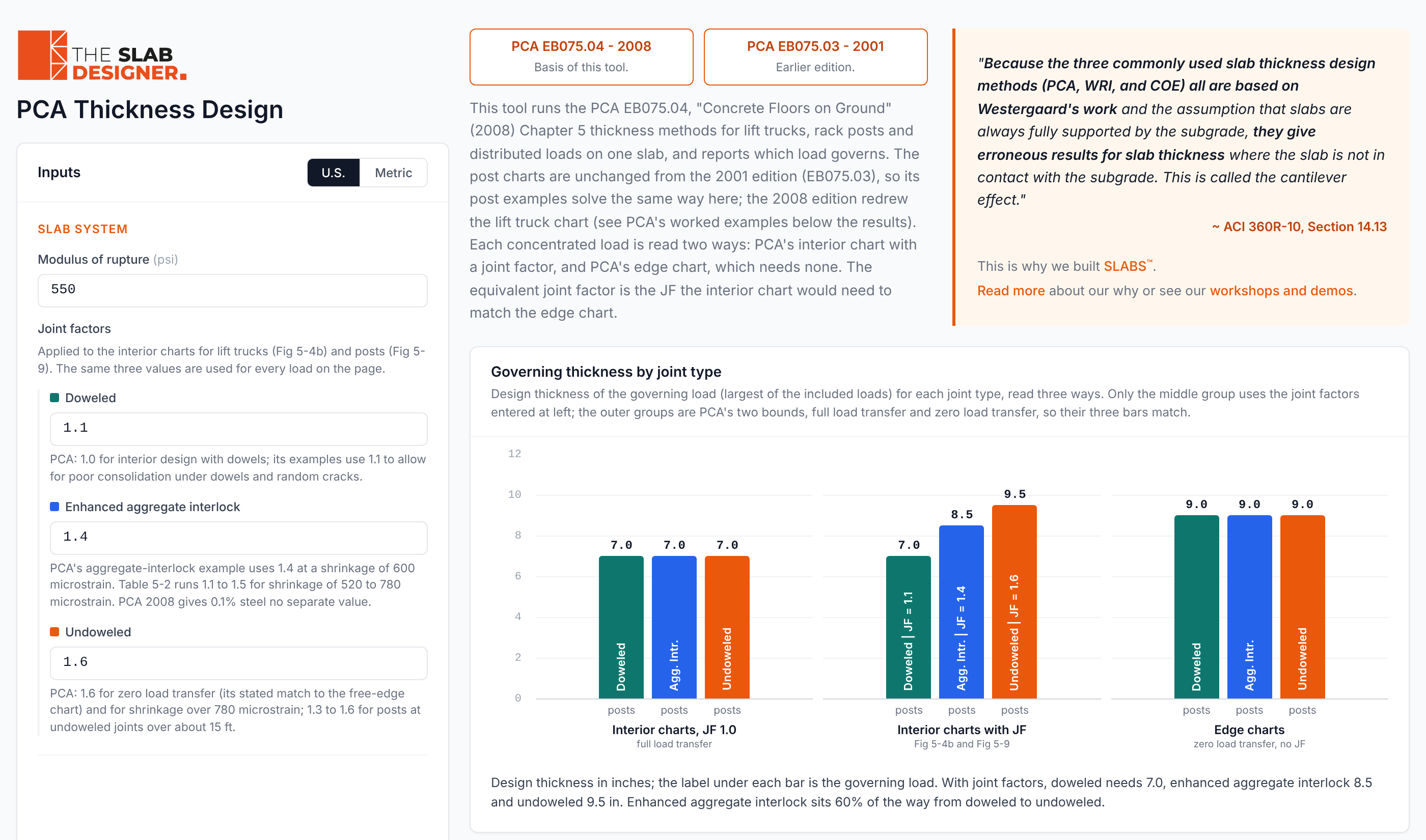
To make the 2008 method reproducible, The Slab Designer digitized PCA's 2008 charts for lift trucks, rack posts, and distributed loads in a free tool (6). The tool reproduces PCA's printed examples from the 2008 and 2001 editions within chart-reading precision, with the single exception noted above (Figure 4). With its default inputs, a 7,000 lb (31 kN) lift truck axle and 11,000 lb (49 kN) rack posts on the same slab, and joint factors of 1.1 for dowels, 1.4 for enhanced aggregate interlock, and 1.6 for undoweled joints, the governing thickness is 7.0 in. (180 mm) doweled, 8.5 in. (220 mm) with enhanced aggregate interlock, and 9.5 in. (240 mm) undoweled (Figure 5).
The PCA method is not endorsed here as a complete design method. It still omits curl, shrinkage, and multiple loads on a panel, all of which affect slab stress and cracking. What the 2001 and 2008 editions did was put a number on the joint, and in doing so they showed that load transfer is a structural design variable and not only a serviceability one: with doweled joints, the same loads can be carried by a thinner slab.
The Gap Between the Guide and Its Source
ACI 360R-10 was published in April 2010, about a year and a half after the 2008 PCA edition. The reason it did not adopt the 2008 edition is not on the public record. ACI committees ballot a document in parts and then as a whole, so the chapters that would have carried the change may have been balloted before the 2008 edition was available; it is also possible that a cement association's recommendation for thicker slabs at undoweled joints met resistance. For the PCA method, the guide cites the 2001 edition, and its worked PCA examples use the 2001 interior charts with no joint factor, including a rack post example, although the 2001 edition already applied joint factors to both lift trucks and posts. The guide does not inform the reader that PCA had revised its method to account for joints.
The consequence is procedural. A designer who selects the PCA method in ACI 360R-10 and follows the appendix example sizes the slab for a load in the panel interior. For an undoweled slab, that thickness can be 2 in. (50 mm) or more thinner than PCA's current method requires for the same loads, and nothing in the steps of the procedure alerts the designer. The relevant warning is in Chapter 14, and it characterizes the result as erroneous.
Implications for Owners and the Standard of Care
When a floor cracks along its joints, spalls under lift trucks, or rocks at its edges, disputes often turn on whether the design met the standard of care, and two responses are common. The first, that concrete cracks, is a fair statement about some shrinkage cracking but not a complete answer where the design method omitted joints, curl, and loss of support, all of which the governing guide discusses, and the first of which the method's own publisher had already addressed. The second, that the design followed ACI 360, does not end the inquiry. The more informative questions are which method and edition were used, whether the joint factor was applied for loads near joints, what load transfer was assumed at each joint type, and whether curl was considered. A design that sized an undoweled slab with interior-only charts did not follow PCA's current method, even if it followed the steps in the ACI appendix. None of this faults engineers who followed the guide as written; the gap is in the guide. As the gap becomes widely known, however, and with the joint factor in PCA's method since 2001, continuing to size undoweled slabs with interior-only charts becomes the designer's choice rather than the guide's. These observations are offered as engineering commentary and not as legal advice.
Recommendations
- Reference the 2008 edition of Concrete Floors on Ground for the PCA method, including its joint factor and free-edge charts.
- Present worked examples with and without load transfer, so that designers see the effect of the joint detail on thickness.
- State, in the chapter where designers choose a thickness method, which load positions and conditions each method covers and which it does not, rather than only in the chapter on curling.
- Require that the design basis on drawings identify the thickness method and edition, loads, support values, and the load transfer assumed at each joint type.
- Do not allow different joint details to share one thickness; undoweled, doweled, and lightly reinforced joints carry load differently.
- Provide guidance for the finite element analysis the guide already describes as appropriate for slabs with discontinuities, including inputs for curl, loss of support, load transfer, and multiple loads on a panel.
Conclusions
The three thickness methods presented in ACI 360R-10 rest on Westergaard's full-support, interior-load idealization, and the guide states in its curling chapter that they give erroneous results where the slab loses contact with the subgrade, which occurs at the joints of nearly every interior floor. Westergaard's own solutions show edge stresses roughly 50% higher than interior stresses before any loss of support. PCA's 1978 and 1983 guidance handled joints by judgment, thickened free edges, and safety factors; it put a number on the problem in 2001 with a joint factor and expanded the treatment in 2008, and its 2008 example shows the joint condition alone is worth more than 2 in. (50 mm) of thickness. ACI 360R-10 cites the earlier edition and works its examples without the joint factor, so a designer following its procedure for an undoweled slab can arrive at a thickness well below PCA's current method. Referencing the current edition, showing examples with and without load transfer, and guiding mechanistic analysis would close the gap.
References
1.ACI Committee 360. Guide to Design of Slabs-on-Ground. ACI 360R-10. American Concrete Institute, Farmington Hills, Mich., 2010.
2.Westergaard, H. M. Stresses in Concrete Pavements Computed by Theoretical Analysis. Public Roads, Vol. 7, No. 2, 1926, pp. 25-35.
3.Packard, R. G. Slab Thickness Design for Industrial Concrete Floors on Grade. IS195. Portland Cement Association, Skokie, Ill., 1976.
4.Portland Cement Association. Concrete Floors on Ground, 3rd ed. EB075. Portland Cement Association, Skokie, Ill., 2001.
5.Farny, J. A., and S. M. Tarr. Concrete Floors on Ground, 4th ed. EB075. Portland Cement Association, Skokie, Ill., 2008.
6.The Slab Designer, LLC. PCA Slab Thickness Design. https://slabs.design/pca. Accessed October 2026.
7.Spears, R. E. Concrete Floors on Ground. EB075.01D. Portland Cement Association, Skokie, Ill., 1978.
8.Spears, R. E., and W. C. Panarese. Concrete Floors on Ground. EB075.02D, 2nd ed. Portland Cement Association, Skokie, Ill., 1983.
Related in This Series
- Article on this topic: The Floor Design Guide That Calls Its Own Results Erroneous
What owners should know about the trap built into the industry's main slab design guide.
- Raised but Not Resolved: An Audit of ACI 360R-10
Audits eight design decisions in ACI 360R-10 for whether each issue raised is carried through to a design method.
- PCA's Airport Pavement Method on Industrial Floors
Validates a rebuild of PCA's 1973 airport method and explains why its flexible inputs do not make it an industrial floor design basis.
- From Westergaard and Meyerhof to Mechanistic-Empirical Design
Summarizes the 2026 Concrete International and Concrete articles that set out why the Westergaard and Meyerhof methods fall short for modern floors and how the SLABS framework addresses it.
- The Modulus of Subgrade Reaction for Slabs-on-Ground
Compares CBR-to-k correlations with a calibrated elastic layered method and evaluates the SSI long-term k-value approach.
Revision history
- November 4, 2026: Added PCA's 2008 joint factor table.
- November 2, 2026: Completed references; added metric units and links to other pieces in the series.
- October 26, 2026: First published on slabs.design/knowledge.
To cite this paper, use the citation printed in the PDF. It includes the revision date, so readers can match your citation to the text you read.