Technical Paper|TSD-12TP
From Westergaard and Meyerhof to Mechanistic-Empirical Design: The Background of the SLABS Framework
Robert Rodden (The Slab Designer, LLC); Juan Pablo Covarrubias (TCPavements-FORTA)
The Slab Designer, LLC | Published November 4, 2026 | Revised November 8, 2026
Abstract
In its first year, The Slab Designer and its collaborators published two articles that together set out the background of the SLABS design framework: "Mechanistic-Empirical Design of Concrete Slabs-on-Ground" in the American Concrete Institute's Concrete International (July 2026), and "Updating Design Methods for Modern Concrete Slab Systems" in the Concrete Society's Concrete (September 2026). The first addresses the three United States thickness methods in ACI 360R-10, all built on Westergaard's full-support solutions. The second addresses Concrete Society Technical Report 34 (TR34), built on Meyerhof's yield-line solutions. This paper summarizes the two together, within the scope of what they published. Both legacy paths assume a slab in full contact with its support, with no curl. Both compare their stresses or moments with a strength measured on a test beam. Neither models joints, slab dimensions, or several loads on a panel as they occur. The paper adds one observation drawn from the rack example in the Concrete article: the legacy methods check the bottom of the slab, while the analysis of a curled, multi-panel slab under back-to-back racks shows, in that example, its highest tensile stresses at the top of the slab, between the rack legs and at the joints. A method that cannot model that stress state cannot be used to design against the cracking it produces; it can only rely on the factor of safety. The paper closes with the framework the articles describe and the recommendations they make.
Keywords: ACI 360R-10, TR34, Westergaard, Meyerhof, yield-line theory, Hetenyi, first crack, curling, EBITD, loss of support, slab capacity, beam flexural strength, macrofibers, top-down cracking, rack loads, ISLAB2000, neural network, mechanistic-empirical design, SLABS
Introduction
Few new companies in this field get their first technical articles into the magazines of the American Concrete Institute and the Concrete Society. The Slab Designer did both in 2026, with co-authors from the University of Illinois, the University of Pittsburgh, and industry (1, 2). The two editors selected the articles for their readers, and that by itself says something about how much interest there is in whether the design methods for industrial floors have kept up with the floors.
The two articles cover the same ground from two directions. The Concrete International article (1) starts from the United States methods in ACI 360R-10 (4) and presents the mechanistic-empirical framework in detail. The Concrete article (2) starts from TR34 (5), the guide most used outside regions that follow ACI, and asks the same questions of yield-line design. Read together, they describe one problem and one proposed solution. This paper summarizes them for the series, keeps to their scope, and cites both. Where it adds something, it says so.
Changing Conditions on the Floor
Both articles begin with what has changed (1, 2). Multi-functional racks and new lift truck equipment are changing the static and dynamic loads on slabs. Small, hard-wheeled lift trucks and robotic equipment have increased spalling and other joint problems, and owners and developers are asking for designs without sawcuts and with armored construction joints. The products in floors have advanced: fiber reinforcement, shrinkage reducers and other admixtures, shrinkage-compensating cements, post-tensioning, vapor retarders, and plate dowels all affect slab design. Cements are finer and blended with pozzolans and inert fillers, which can raise water demand and affect volume stability and curl (1, 2).
None of these changes is an input to the legacy thickness methods.
Two Legacy Paths
Table 1 sets the two paths side by side.
Table 1. The Two Legacy Design Paths (after 1, 2)
| ACI path | TR34 path | |
|---|---|---|
| Foundation | Westergaard (1926): elastic stresses for interior, edge, and corner loads on a fully supported slab (3) | Meyerhof (1962): yield-line solutions for the ultimate load capacity of the slab (6) |
| Methods | PCA (now ACA), WRI, and COE (8, 9, 10) | TR34, 4th edition (5); line and uniform loads by Hetényi's beam on elastic foundation (7) |
| Design objective | Limit the tensile stress under the load to a fraction of the modulus of rupture | Limit the load to the ultimate (collapse) capacity, with partial factors; line and uniform loads checked against first cracking |
| Support | Full, uniform contact | Full contact, no curl, as Meyerhof states |
| Curl | Not an input | Acknowledged; recommendations to reduce shrinkage and in-service remedies only |
| Strength | Modulus of rupture of a beam | Beam flexural strength, with fiber residual capacity in the sagging regions |
| Load transfer | Partial (COE credits a factor of 0.75) | On the capacity side only: 15% from aggregate interlock plus dowel capacity, capped at 50% of the load |
Westergaard and ACI 360R-10
Westergaard established slab-on-ground analysis in 1926 with stresses for interior, edge, and corner loads on a fully supported elastic slab (3). The three United States methods built on that foundation, the American Cement Association (formerly PCA), WRI, and Corps of Engineers methods, form the backbone of ACI PRC-360R-10, and all three carry Westergaard's assumption of full, uniform subgrade contact (1). The guide is explicit about the consequence (4, Section 14.13): "Because the three commonly used slab thickness design methods (PCA, WRI, COE) all are based on Westergaard's work and the assumption that slabs are always fully supported by the subgrade, they give erroneous results for slab thickness where the slab is not in contact with the subgrade. This is called the cantilever effect."
Meyerhof and TR34
TR34 uses yield-line theory through Meyerhof's solutions to estimate the ultimate load capacity of the slab (5, 6). Line loads and uniformly distributed loads are checked with Hetényi's beam on elastic foundation against first-cracking strength (7). The Concrete article puts the difference in design objective plainly (2). TR34's limit state method answers the question of the ultimate collapse load of the slab. It assumes the sagging (bottom) moment regions have already cracked and redistributed moment, mobilizing the post-crack residual capacity of fibers or fabric, while capping the hogging (top) moment at the cracking moment of plain concrete. The question that governs modern floor design is a different one: at what load does the first flexural crack appear, under realistic curl, loss of support, load transfer, and slab geometry? Most owners expect crack-free slabs, top and bottom, so the design objective for an industrial slab-on-ground is preventing the first flexural crack anywhere in the section (2).
That is not to say yield-line theory cannot produce reasonable thicknesses and performance with appropriate partial factors (2). It is to say that the callbacks contractors receive (joint deterioration, corner cracking, faulting, curl-related distress, excessive movement under wheel loads, and surface roughness) are conditions yield-line theory was never expected to predict (2). Meyerhof's approach also leaves out slab dimensions, loss of foundation support, and the difference between slab and beam flexural strength (2).
What Both Paths Leave Out
Curl is the expected condition
Upward curl is not an exceptional case. It is the expected condition for indoor slabs-on-ground, which dry from the top and lift at their edges and corners (1, 2). The magnitude depends on slab thickness, the concrete mixture, curing, joint spacing, the foundation layers, and the environment (1). Finer cements and interground limestone have increased shrinkage and warping in markets where it was not historically noticed, and hot, arid climates with high-pozzolan cements, common in many Latin American industrial markets, can push the equivalent gradient beyond −2.0°F/in. (−40°C/m) (1).
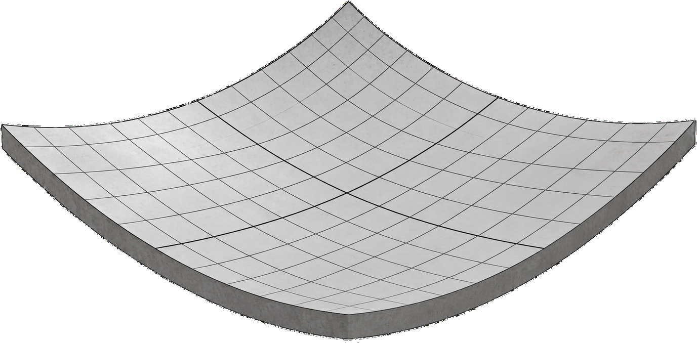
Neither path designs for it. ACI 360R-10 acknowledges the cantilever effect but its methods have no input for it (1, 4). TR34 acknowledges that moisture curling results from differential shrinkage but provides only recommendations for reducing drying shrinkage and in-service remedies such as under-slab grouting, with no design guidance for lift-off at edges and corners or for the stress state curl induces (2, 24). Meyerhof states that his analysis assumes full contact of base and slab and no curling (6). Curled slabs develop loss of support and stress concentration when loaded near joints and corners, conditions entirely outside both the Westergaard solutions and yield-line analysis (2).
A beam is not a slab
Both paths take their strength from a beam. The ACA and WRI methods derive allowable stress from the modulus of rupture, effectively treating the slab as a standard flexural beam, which ignores the differences in geometry, support, and loading, the three-dimensional nature of slab behavior, and the redistribution afforded by the slab's interaction with its foundation (1). Simply supported beams loaded at the center point and at the third points have been known for about 100 years to give flexural strengths 15 to 25% apart, with strength also changing with beam depth (14), and recent work explains why flexural strength is not a material property at all (14, 15). Using beam strength to estimate slab capacity has been shown experimentally to be a gross and overly conservative simplification (16), and many macrofibers, steel and synthetic, measurably increase slab flexural and ultimate capacity (16, 17). Beckett was among the first to quantify this for steel fibers in ground slab tests (18); Roesler et al. confirmed it for macro-synthetic fibers (17). Accounting for the slab's flexural capacity and the fiber contribution can change the required thickness directly and transparently (2).
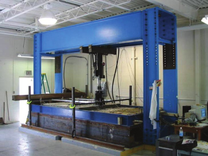
Real loads on real slabs
Slab dimensions and deflections are not directly considered in TR34 but matter for extended joint spacings and for short slabs, for example less than 20 ft (6 m) (2). Traditional methods were calibrated primarily for uniform or simple concentrated loads and offer limited guidance where several loads in proximity interact (1). Finite element analysis can compute stresses and deflections at both the top and the bottom of a multi-slab system for any combination of mechanical and environmental loads, including their interaction and the loss of support (2).
Which Face Cracks
This section adds an observation to what the articles published, using the rack example in the Concrete article (2, Figure 3). The example is a 4 x 3 panel system of curled slabs carrying back-to-back racks, analyzed with ISLAB2000 (Figure 3).
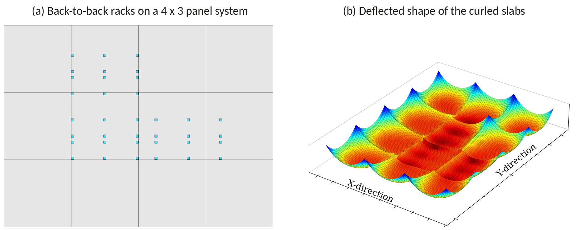
Figure 4 shows the two faces of the slab. On the bottom (Figure 3a), the tensile concentrations sit under the rack legs. That is the stress the legacy methods compute: a Westergaard interior stress at the bottom of the slab under the load, and at times at the edge of a flat, fully supported slab. On the top (Figure 3b), the tension is between the rack legs and at the joints, and in this example that plot carries the highest stresses and the largest tensile area of the two.
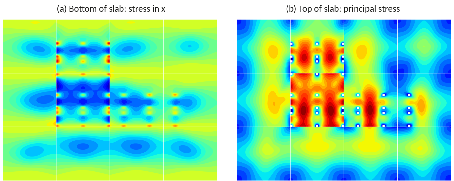
The governing risk in this example is top-down cracking, between the legs rather than under them. The Westergaard-based methods do not compute top tension at all. Meyerhof's mechanism includes a hogging crack at the top, but around a single load on a slab in full contact with no curl; it does not compute the top tension that develops between the legs of back-to-back racks on a curled, jointed, multi-panel slab. That stress state is outside the scope of both legacy paths. If a method cannot model a stress state, it cannot be used to design against the cracking that stress state produces. The only protection it can offer is whatever is left of its factor of safety.
Conservative or Unconservative
Because the legacy methods do not model curl, joints, slab size, or loss of support, the error in their stresses goes both ways. Mechanistic-empirical analysis has shown that where curl is significant and joints have poor load transfer, the traditional methods underpredict critical stresses by 20 to 50%, producing unconservative designs prone to early cracking (1, 2). For well-supported slabs with good load transfer, they can overestimate stresses by 15 to 25%, producing slabs thicker than necessary (1, 2). A method that cannot model curl, slab dimensions, joints, and loss of support has no way of knowing the real factor of safety of the design it produces (2).
The Transition Pavements Already Made
Highway and airfield engineers faced the same limitations decades ago (2). Rather than continuing to refine design equations with empirical adjustments, the United States concrete pavement industry adopted mechanistic-empirical design based on finite element analysis. The AASHTO Mechanistic-Empirical Pavement Design Guide, now Pavement ME Design, predicts slab cracking, joint faulting, and roughness by modeling the effects of design features, foundation layers, and environment on critical stresses and deflections, using neural networks trained on ISLAB2000 (11, 12). Its performance models were calibrated to highway Long-Term Pavement Performance data. The mechanistic stress calculations transfer directly to floors; calibration of the performance prediction to industrial floor data is ongoing (2).
The Framework
The SLABS framework, presented in Concrete International (1) and summarized in Concrete (2), evolves from the Westergaard tradition rather than discarding it. ISLAB2000 keeps Westergaard's plate on a Winkler foundation as its conceptual basis and extends it in three directions: explicit modeling of curl and the resulting loss of support, characterization of multiple foundation layers, and load transfer across joints by aggregate interlock, tie bars, and dowels, with joint opening from shrinkage and slab-base friction (1, 12). ISLAB2000 has been verified against instrumented slab measurements (13) and large-scale slab capacity tests (16, 17). Table 2 summarizes the inputs.
Table 2. Inputs to the SLABS Framework (from 1, 2)
| Input | How it is handled |
|---|---|
| Curl | Equivalent built-in temperature difference (EBITD) (19), which can be estimated from the curl number (20); among the most influential parameters on critical stress |
| Support | Composite k-value from a multi-layer elastic solution with a rigid-plate correction (21) |
| Load transfer | Joints modeled as shear springs; dowels explicit; stress at a doweled loaded edge 15 to 30% below a free edge; dowel size and spacing for 90% LTE by the EIDM (22) |
| Loads | Counterbalanced and reach truck lift trucks, single- and multi-leg rack posts with back-to-back interaction, distributed storage, seismic combinations |
| Materials | Macrofiber residual strength, effective prestress for post-tensioning, shrinkage reduction and vapor retarder practice through EBITD, slab-base friction |
| Capacity | Critical tensile stress compared with an estimated slab capacity rather than the beam flexural strength (16, 17, 25, 26) |
| Speed | Neural network surrogate trained on more than 1.3 million ISLAB2000 runs, mean absolute error below 2% on peak tensile stress |
Two consequences stand out in the articles. A stiffer base lowers the required thickness under load alone but amplifies curling stress and edge support loss, so the common assumption that a low k-value is always conservative may not hold once curl and loss of support are modeled (1, 2). And TR34 credits load transfer only on the capacity side, while the framework computes the stress state at the loaded joint directly (2).
Results
A comparison of seven common slab-on-ground systems analyzed with SLABS found that thickness alone is a poor indicator of performance (2, 23). The thickest slab evaluated, an unreinforced 250 mm (10 in.) section, could be 30% thinner once load transfer at the joints and curl reduction were considered, under the same loading and support (2). The articles' practical guidance is that most projects will get either a thinner slab, where interior loads govern and load transfer is good, or a better-justified thicker one, where edge loads govern with high curl or poor load transfer (1).
Recommendations From the Articles
The articles recommend (1, 2):
- Design for the first flexural crack, top or bottom, against the slab's flexural capacity rather than its ultimate capacity or a beam strength.
- Adopt EBITD as a standard design input, using regional curl number measurements where project data are not available, and encourage owners to collect curl data.
- Characterize composite k-values with modern mechanistic-empirical methods and verify them by plate load testing at subgrade acceptance.
- Specify doweled contraction and construction joints as the default for medium- and heavy-duty slabs.
- Use the framework to weigh fiber reinforcement as a thickness-reduction strategy against its cost.
- Run parallel designs, the method of record and the mechanistic-empirical framework with conservative inputs, to build familiarity before full adoption.
The Concrete International article adds a note for real estate agents and prospective tenants: the structure of a slab is not defined by its thickness alone, and tenants should ask for certification that differential deflection across joints under their lift trucks will meet ACI 360R-10's guidance of 0.010 in. (0.25 mm) for small, hard wheels and 0.020 in. (0.51 mm) for large rubber wheels (1).
Conclusions
The two articles reach the same conclusion from the two main design traditions. The Westergaard methods in ACI 360R-10 and the Meyerhof method in TR34 both assume a slab in full contact with no curl, take their strength from a beam, and size the slab for one load at a time without its joints or dimensions. Every year, owners and contractors deal with joint deterioration, corner cracking, and curl-related distress in floors that satisfied the governing method, passed design review, and met the specified strength (2). The rack example adds the clearest illustration: the legacy methods check the bottom of the slab under the load, while in this example the highest tension in the curled rack aisle is at the top, between the legs and at the joints. A method that cannot model a stress state cannot design against the cracking it causes; it can only rely on the factor of safety. As the Concrete article concludes, the question is no longer whether these inputs matter, but whether the industry should keep relying on methods that do not consider them (2).
References
1.Covarrubias, J. P., R. Rodden, J. Roesler, L. Khazanovich, J. Olavarría, and N. Parkes. Mechanistic-Empirical Design of Concrete Slabs-on-Ground. Concrete International, Vol. 48, No. 7, July 2026, pp. 45 to 53.
2.Roesler, J., J. P. Covarrubias, L. Khazanovich, J. Olavarría, N. Parkes, and R. Rodden. Updating Design Methods for Modern Concrete Slab Systems. Concrete, The Concrete Society, Vol. 60, No. 7, September 2026, pp. 14 to 17.
3.Westergaard, H. M. Stresses in Concrete Pavements Computed by Theoretical Analysis. Public Roads, Vol. 7, No. 2, 1926, pp. 25 to 35.
4.ACI Committee 360. Guide to Design of Slabs-on-Ground. ACI PRC-360R-10. American Concrete Institute, Farmington Hills, Mich., 2010.
5.The Concrete Society. Concrete Industrial Ground Floors: A Guide to Design and Construction. Technical Report 34, 4th ed. Camberley, U.K., 2013 (4th impression 2018).
6.Meyerhof, G. G. Load Carrying Capacity of Concrete Pavements. Journal of the Soil Mechanics and Foundations Division, ASCE, Vol. 88, No. SM3, 1962, pp. 89 to 116.
7.Hetényi, M. Beams on Elastic Foundation. University of Michigan Press, Ann Arbor, 9th printing, 1971.
8.Farny, J. A. Concrete Floors on Ground. Portland Cement Association (now American Cement Association), 2001.
9.Wire Reinforcement Institute. Design Procedure for Industrial Slabs. Interim Report. McLean, Va., 1973.
10.U.S. Army Corps of Engineers, Naval Facilities Engineering Systems Command, and Air Force Civil Engineer Center. Design of Concrete Floor Slabs-on-Ground for DOD Facilities. 2025.
11.American Association of State Highway and Transportation Officials. Mechanistic-Empirical Pavement Design Guide: A Manual of Practice, 3rd ed. Washington, D.C., 2020.
12.Khazanovich, L., H. T. Yu, S. Rao, K. Galasova, E. Shats, and R. Jones. ISLAB2000: Finite Element Analysis Program for Rigid and Composite Pavements, User's Guide. ARA, Inc., Champaign, Ill., 2000.
13.Yu, H. T., L. Khazanovich, M. I. Darter, and A. Ardani. Analysis of Concrete Pavement Responses to Temperature and Wheel Loads Measured from Instrumented Slabs. Transportation Research Record 1639, 1998, pp. 94 to 101.
14.Gonnerman, H. F., and E. C. Shuman. Flexure and Tension Tests of Plain Concrete. Director's Report, Portland Cement Association, Series 171, 209, 210, 1928, pp. 137 to 200.
15.Saha, S., J. Roesler, and O. Lopez-Pamies. Breaking Four-Point and Three-Point Bending Tests. arXiv:2601.04565, January 2026.
16.Roesler, J. R., D. A. Lange, S. A. Altoubat, K.-A. Rieder, and G. R. Ulreich. Fracture of Plain and Fiber-Reinforced Concrete Slabs under Monotonic Loading. Journal of Materials in Civil Engineering, ASCE, Vol. 16, No. 5, 2004, pp. 452 to 460.
17.Roesler, J. R., S. A. Altoubat, D. A. Lange, K.-A. Rieder, and G. R. Ulreich. Effect of Synthetic Fibers on Structural Behavior of Concrete Slabs-on-Ground. ACI Materials Journal, Vol. 103, No. 1, 2006, pp. 3 to 10.
18.Beckett, D. Comparative Tests on Plain, Fabric Reinforced and Steel Fibre Reinforced Concrete Ground Slabs. Concrete, Vol. 24, No. 3, 1990, pp. 43 to 45.
19.Rao, S., and J. R. Roesler. Characterizing Effective Built-In Curling from Concrete Pavement Field Measurements. Journal of Transportation Engineering, Vol. 131, No. 4, 2005, pp. 320 to 327.
20.Face, A., and N. Parkes. Addressing Concrete Slab Curl Numbers. For Construction Pros, May 25, 2026.
21.Cañas Silva, J. T. Método de Cálculo del Módulo de Reacción "K" para un Sistema de Fundación Multicapas para Pavimentos de Hormigón. Memoria de Título, Universidad de Los Andes, Santiago, Chile, 2010.
22.Parkes, N., J. Olavarría Bastidas, and R. Rodden. Optimize Concrete Slab Dowel Design. For Construction Pros, October 2025.
23.Rodden, R., J. P. Covarrubias, and N. Parkes. Concrete Slab-on-Ground Thickness Requirements from Modern Design. For Construction Pros, July 20, 2026.
24.Ioannides, A. M., and L. Khazanovich. Nonlinear Temperature Effects on Multilayered Concrete Pavements. Journal of Transportation Engineering, Vol. 124, No. 2, 1998, pp. 128 to 136.
25.Brand, A. S., A. N. Amirkhanian, and J. R. Roesler. Flexural Capacity of Full-Depth and Two-Lift Concrete Slabs with Recycled Aggregates. Transportation Research Record 2456, 2014, pp. 64 to 72.
26.Roesler, J. R., V. G. Cervantes, and A. N. Amirkhanian. Accelerated Performance Testing of Concrete Pavement with Short Slabs. International Journal of Pavement Engineering, Vol. 13, No. 6, 2012, pp. 494 to 507.
Related in This Series
- Article on this topic: If You Can't Model It, You Can't Prevent It
A plain-language summary of our Concrete International and Concrete articles, and why, in our rack example, the highest stress is where the legacy methods don't look.
- Raised but Not Resolved: An Audit of ACI 360R-10
Audits eight design decisions in ACI 360R-10 for whether each issue raised is carried through to a design method.
- The Thickness Methods of ACI 360R-10 and Their PCA Lineage
Traces how PCA added a joint factor in 2001 and 2008 that ACI 360R-10's thickness procedure still omits.
- PCA's Airport Pavement Method on Industrial Floors
Validates a rebuild of PCA's 1973 airport method and explains why its flexible inputs do not make it an industrial floor design basis.
- Light Reinforcement Through Sawcut Joints: Tolerances and the JRCP Record
Thickness tolerances push as-built steel ratios past 0.1%, and the highway record of JRCP shows where that detail leads.
Revision history
- November 8, 2026: Removed an unsupported reference to impact stresses; added inch-pound units.
- November 4, 2026: First published on slabs.design/knowledge.
To cite this paper, use the citation printed in the PDF. It includes the revision date, so readers can match your citation to the text you read.