Article|TSD-05A
The Floor Design Guide That Calls Its Own Results Erroneous
What developers and owners should know about how warehouse slabs are designed, and why the industry's main guide has a trap built into it.
The Slab Designer, LLC | Published October 26, 2026 | Revised November 4, 2026
A warehouse floor is one of the largest single line items in an industrial building and one of the few that the tenant touches every minute of every shift. When it cracks, curls, or its joints break down, the costs land on the owner: repairs while the building is operating, lift truck damage, flatness problems for high racks, and, too often, a dispute over who is responsible.
In those disputes, one line comes up again and again: "It's concrete. It's going to crack." That line assumes the floor was designed with methods that reasonably represent how a floor behaves. This article explains why that assumption deserves a closer look, using the words of the design guide itself.
The guide engineers design to
Most industrial floors in the United States are designed by reference to ACI 360R-10, Guide to Design of Slabs-on-Ground, published by the American Concrete Institute in 2010. The building code, ACI 318, does not cover ordinary slabs on ground; its commentary sends designers to ACI 360 instead. So while ACI 360R-10 is a guide and not a code, it is the document a designer, a peer reviewer, or an expert witness will point to as the standard of practice.
For setting slab thickness, ACI 360R-10 presents three methods as "generally accepted": the Portland Cement Association (PCA) method, now published by the American Cement Association (ACA); the Wire Reinforcement Institute (WRI) method; and the U.S. Army Corps of Engineers (COE) method. Each comes with charts and worked examples in an appendix. An engineer can follow any one of them step by step and produce a thickness.
All three rest on a 100-year-old idea
All three methods trace back to the work of Harald Westergaard in the 1920s. Westergaard found a way to calculate stresses in a concrete pavement with pencil and paper. To do that, he had to assume an idealized slab: one with no joints, resting in full contact with perfectly uniform soil, with the load placed well away from any edge. Those assumptions made the math possible. They also leave out the three things that most often cause trouble in real floors (Figure 1):
- Joints. Every slab has them. A load at a joint that cannot share load with the next panel is carried by the edge alone, and the stress is much higher than the same load in the middle of a panel.
- Curl. As the top of a slab dries faster than the bottom, the edges and corners lift off the ground. ACI 360R-10 itself reports curling stresses of 200 to 450 psi (1.4 to 3.1 MPa), the same order as the load stresses a design allows.
- Loss of support. Where the slab has curled up off the ground, a lift truck wheel or rack post at the edge is supported by a cantilever, not by the soil.
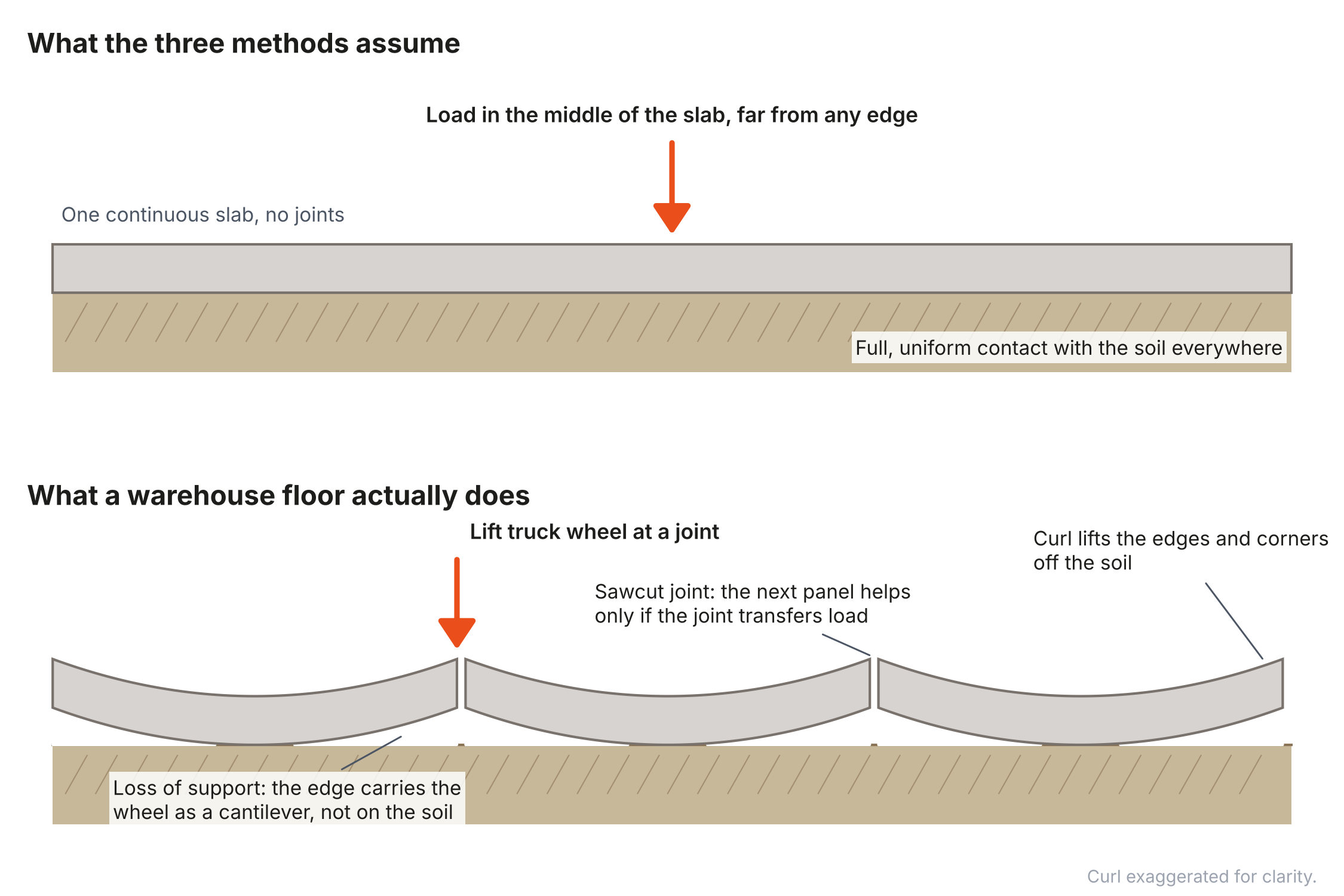
None of these is news. ACI 360R-10 has chapters on joints, load transfer, curling, and shrinkage that explain why they matter. It does not give the designer a way to put them into the thickness calculation.
What the guide says about its own methods
Here is how ACI 360R-10 describes the three methods in its chapter on curling, Section 14.13:
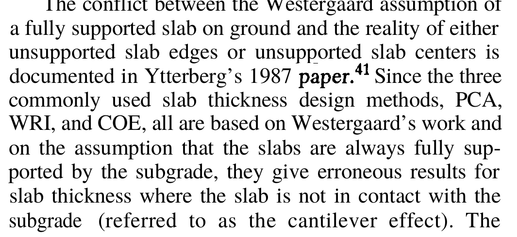
"Because the three commonly used slab thickness design methods (PCA, WRI, and COE) all are based on Westergaard's work and the assumption that slabs are always fully supported by the subgrade, they give erroneous results for slab thickness where the slab is not in contact with the subgrade."
Elsewhere the guide notes that most of the methods "do not provide for loading at free edges and corners" and that finite element analysis can be used to analyze slabs, "particularly those with discontinuities." It also says, "Curl-induced stresses are not considered." Every real slab has joints, so every real slab has discontinuities.
Put plainly, the guide recommends three methods and then says they give erroneous results wherever the slab has curled off the ground, which is at the joints and edges of nearly every interior floor. The methods do work for a load in the middle of a panel on a slab that has not curled. In a working warehouse, lift trucks cross joints all day and rack posts sit near them, so that case is the exception.
PCA saw the problem and fixed part of it
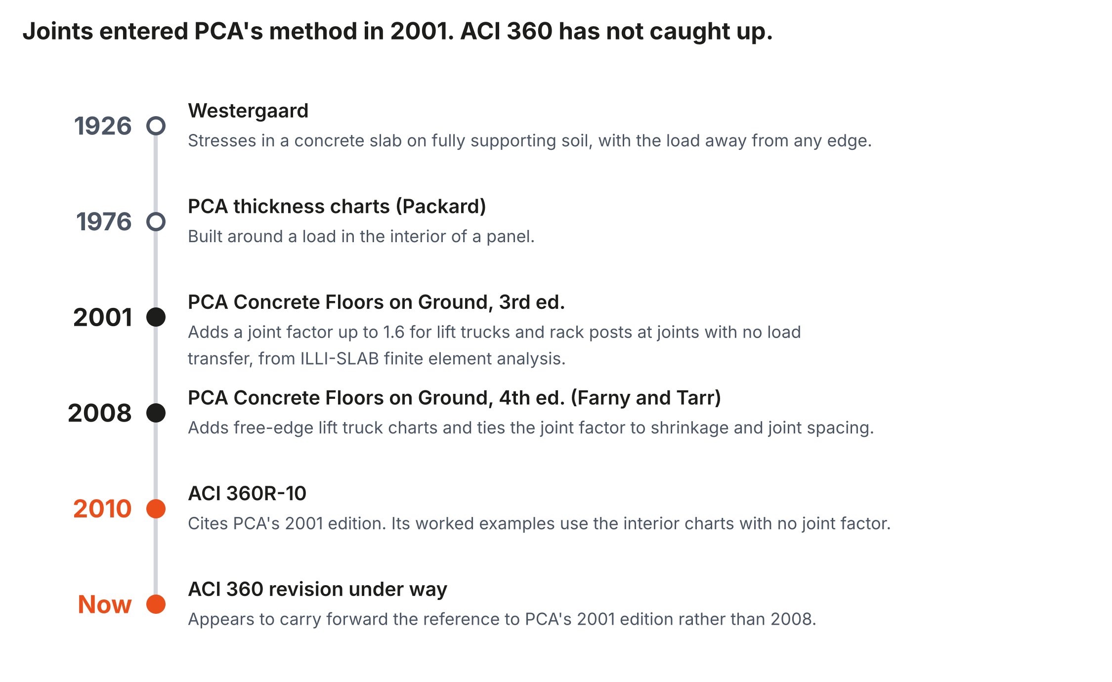
The PCA method is the most widely used of the three, and its history shows the gap was recognized long ago (Figure 4).
- 1976: PCA's thickness charts, developed by Robert Packard, are built around a load at the interior of a panel.
- 1978: The first edition of Concrete Floors on Ground, by Ralph Spears, uses those charts and assumes a panel acts as part of one continuous slab when its joints have adequate load transfer. Where lift trucks cross a free edge, such as an isolation joint at a doorway, it calls for thickening the slab 50%, and it asks designers to choose safety factors that allow for rack legs near joints.
- 1983: The second edition, by Spears and William Panarese, keeps the interior charts and the continuous-slab assumption but cuts the free-edge thickening to 25%, tapered over 5 ft, and notes that dowels "may be preferable for load transfer."
- 2001: The third edition of Concrete Floors on Ground replaces judgment with a number: a joint factor of up to 1.6 for lift trucks and rack posts at joints with no load transfer, based on ILLI-SLAB finite element analysis showing edge stresses 50% to 60% higher than interior stresses.
- 2008: The fourth edition, by James Farny and Scott Tarr, adds free-edge charts for lift trucks and ties the joint factor to shrinkage and joint spacing.
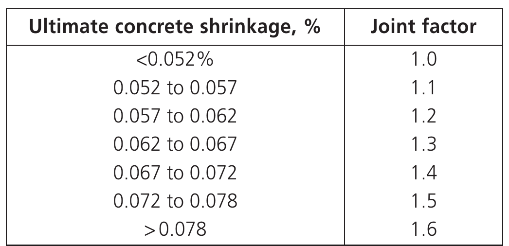
The 2008 edition explains why: the original charts give stresses "at the interior of a slab, assuming that the load is applied at some distance from any joint," and "when the load is applied at the joints the resulting stress can be significantly higher." It tells designers to apply a joint factor between 1.0, when dowels are properly installed and full load transfer is assured, and 1.6, "when free edge loading is anticipated and no load transfer is present."
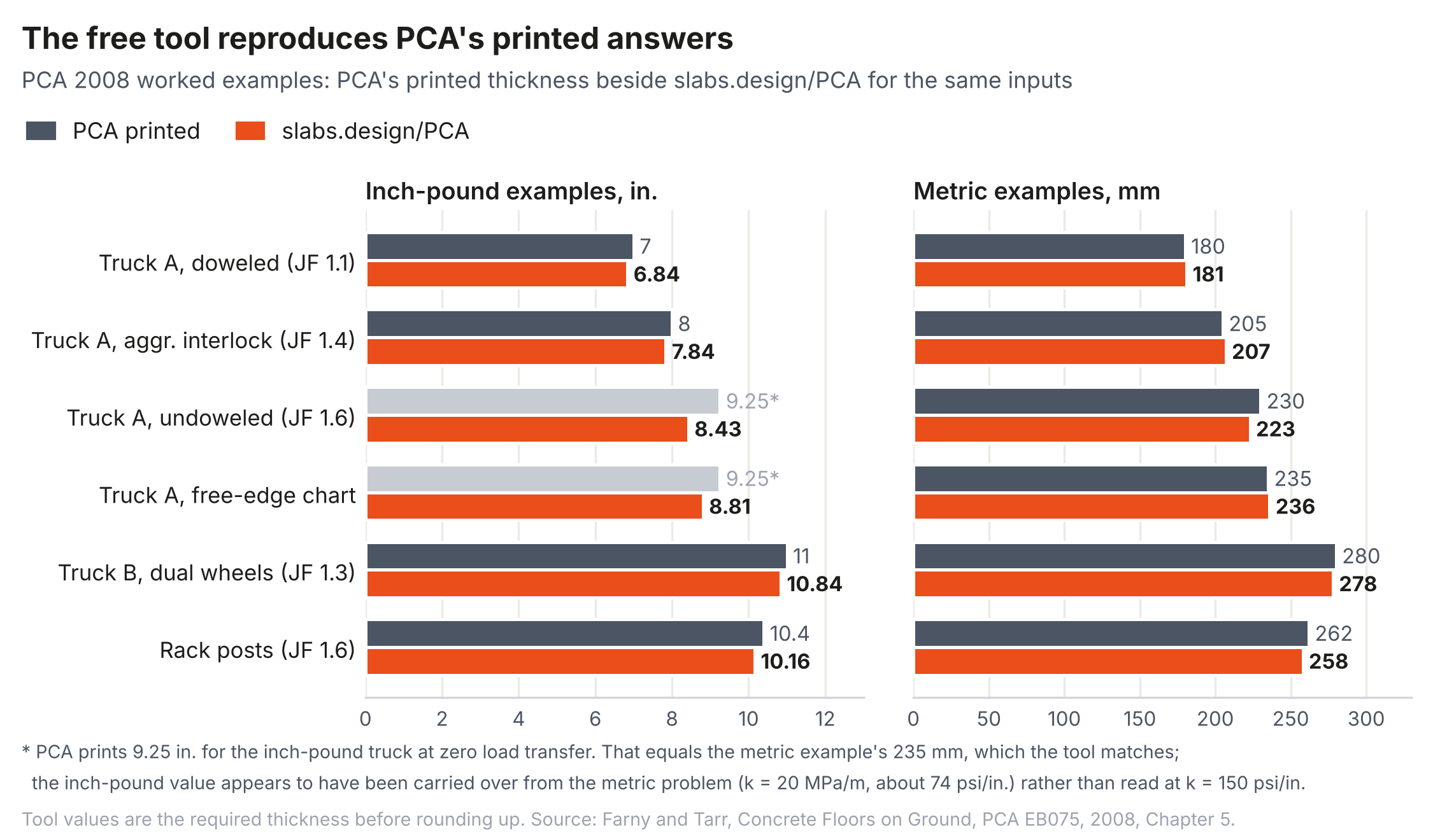
The effect on thickness is not small. In PCA's own 2008 metric lift truck example, with the same truck, concrete, and soil in every case, the slab comes out at 180 mm (about 7 in.) with doweled joints, 205 mm (8 in.) with aggregate interlock at low-shrinkage concrete and short joint spacing, and 235 mm (9.25 in.) at a free edge with no load transfer. The joint detail is worth more than 2 in. (50 mm) of concrete.
That cuts both ways, and the good news is the first way. Where an interior-load design framework was used to justify thickness, a floor with dowels at every joint has a factor of safety much closer to that intended by the engineer of record than does one without dowels, or one counting on enhanced aggregate interlock. The same floor without load transfer at its joints is the one quietly eating into its factor of safety. The fix is not thicker floors. It is joints that carry their share.
A free way to see the effect
To make the 2008 method easy to check, The Slab Designer has digitized it. Our free PCA Slab Thickness Design tool at https://slabs.design/pca reads PCA's 2008 charts for lift trucks, rack posts, and distributed loads, applies a joint factor for each joint type, reports which load governs, and reproduces PCA's printed worked examples from the 2008 and 2001 editions (Figure 5).
We do not endorse the PCA method for design. It still leaves out curl, shrinkage, and more than one load on a panel at a time, all critical to realistic analysis of slab stresses and cracking. What the 2008 edition does do is put a number on the joint. Dowels are usually credited with controlling deflection, but the joint factor shows they also matter structurally: with doweled joints, the same loads can be carried by a thinner slab.
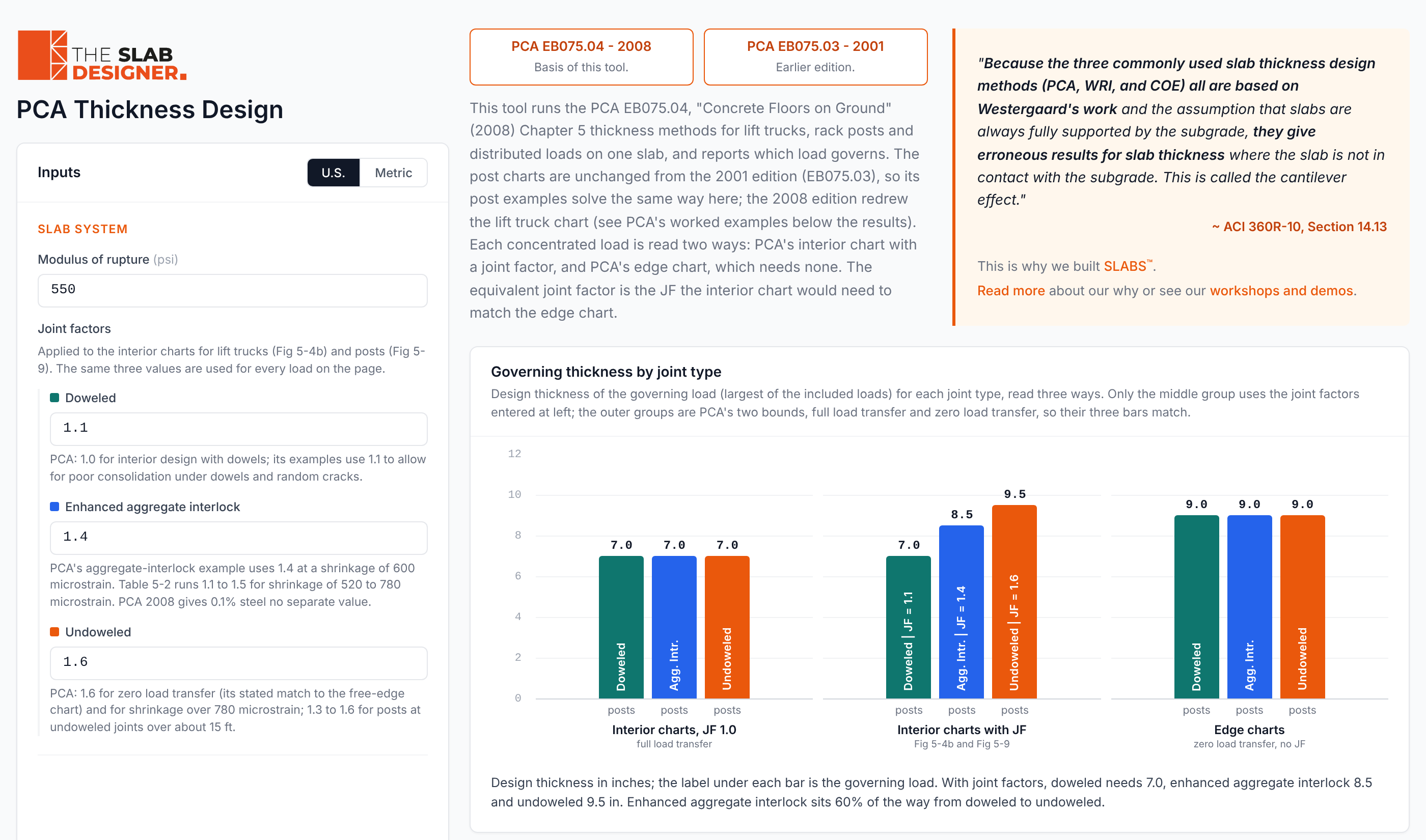
Joints that rely on aggregate interlock, including enhanced aggregate interlock systems, fall in between, and closer to undoweled than to doweled. With the tool's default inputs, a 7-kip lift truck and 11-kip rack posts on the same slab, and joint factors of 1.1 doweled, 1.4 enhanced aggregate interlock, and 1.6 undoweled, the governing thickness is 7.0 in. (180 mm) with dowels, 8.5 in. (220 mm) with enhanced aggregate interlock, and 9.5 in. (240 mm) undoweled (Figure 6).
Where the trap is
ACI 360R-10 was published in April 2010, about a year and a half after the 2008 PCA edition. Why it did not pick up the 2008 edition is not on the public record. ACI committees ballot a document in parts and then as a whole, so the chapters that would have carried the change may have been balloted before the 2008 edition came out. It is also possible that a cement association's recommendation for thicker slabs where joints have no dowels was not welcome news. Either way, for the PCA method the guide cites the 2001 edition, and its worked examples use the 2001 interior charts with no joint factor, including a rack post example, even though the 2001 edition already applied joint factors to both lift trucks and posts. The guide never tells the reader that PCA had changed its method to account for joints.
That is the trap. A designer who follows ACI 360R-10 to the letter, chooses the PCA method, and works through the example in the appendix will size a slab for a load in the middle of a panel. If that slab has undoweled joints, it can be inches thinner than PCA's own current method requires. Nothing in the steps the guide lays out will warn the designer. The warning is in a different chapter, and it says the result is erroneous.
The other two methods share the same limits. The COE method builds a fixed 25% reduction for load transfer into every joint, with or without dowels, and does not cover rack posts or stored loads. The WRI charts cover interior loads only, and the guide cites no WRI publication for the method.
Why this matters to owners
Developers, owners, and tenants do not expect a floor designed with guidance that the guide itself calls erroneous for the conditions the floor will see at its joints. When a floor cracks along the joints, the joints spall under lift trucks, or the edges rock and break down, the question in a dispute is often whether the design met the standard of care.
Two points are worth having in mind when that question comes up. This is the author's engineering view, not legal advice.
- "It's concrete, it's going to crack" is a fair statement about some shrinkage cracking. It is not a complete answer when the design method left out joints, curl, and loss of support. The governing guide discusses all three, and the method's own publisher had already added joints to its method, though not curl or loss of support.
- "We followed ACI 360" is not the end of the inquiry. The more useful questions are which method was used, which edition, whether the joint factor was applied for loads near joints, what load transfer was assumed at each joint type, and whether curl was considered. A design that sized an undoweled slab with interior-only charts did not follow PCA's current method, even if it followed the steps in the ACI appendix.
None of this faults engineers who followed the guide as written. The gap is in the guide. That answer has a shelf life, though. The joint factor has been in PCA's method since 2001, and as the gap becomes widely known, an engineer who keeps sizing undoweled slabs with interior-only charts owns that choice.
What the guide should do
The fix is not complicated. The guide should reference the 2008 edition, including the joint factor and the free-edge charts, with examples worked with and without load transfer so a designer can see the difference. It should also give real guidance for the finite element analysis it already calls appropriate for slabs with joints, the only practical way to include curl, loss of support, and multiple loads on one panel.
What to ask for on your next project
Owners and developers do not need to become slab designers to protect themselves. A few questions, asked early and written into the contract documents, go a long way.
- Ask for the design basis on the drawings: the thickness method and edition, the loads, the soil support values, and the load transfer assumed at each joint type.
- Ask whether loads near joints were designed for. For PCA, that means the joint factor. For a finite element design, it means the load transfer and curl that were modeled.
- Do not let different joint details share one thickness. An undoweled slab, a doweled slab, and a slab with light steel through the joints carry load differently and need separate designs.
- Compare options at equal capacity. A doweled slab is often thinner and less expensive to build than an undoweled slab designed correctly, and its joints cost less to maintain.
- Keep the design file. If a dispute arises years later, the method, edition, and assumptions used will matter.
The industry has known for more than 25 years that joints change how a floor carries load. PCA wrote it into its method. The tools to design for it are now readily available. The remaining step is for the guide that engineers rely on to say so in the place where they do the design.
Sources
American Concrete Institute Committee 360, ACI 360R-10, Guide to Design of Slabs-on-Ground, Farmington Hills, MI, 2010. Quotations from Sections 1.4.3, 7.2, and 14.13; examples from Appendix 1.
Farny, J. A., and Tarr, S. M., Concrete Floors on Ground, EB075, fourth edition, Portland Cement Association, Skokie, IL, 2008. Quotations from Chapter 5.
Portland Cement Association, Concrete Floors on Ground, EB075, third edition, Skokie, IL, 2001.
Spears, R. E., Concrete Floors on Ground, EB075.01D, Portland Cement Association, Skokie, IL, 1978.
Spears, R. E., and Panarese, W. C., Concrete Floors on Ground, EB075.02D, second edition, Portland Cement Association, Skokie, IL, 1983.
Colley, B. E., and Humphrey, H. A., "Aggregate Interlock at Joints in Concrete Pavements," Highway Research Record 189, 1967.
The Slab Designer, LLC, PCA Slab Thickness Design, free online tool based on Farny and Tarr (2008), https://slabs.design/pca, 2026.
Related in This Series
- Technical paper on this topic: The Thickness Methods of ACI 360R-10 and Their PCA Lineage
Traces how PCA added a joint factor in 2001 and 2008 that ACI 360R-10's thickness procedure still omits.
- The Design Guide a New Engineer Can't Design From
A new engineer follows ACI 360R-10 step by step and finds the places it raises an issue and stops.
- Your Warehouse Floor Is Not a Runway
Why an airport design method ended up sizing forklift floors, and why matching inputs is not the same as matching the problem.
- If You Can't Model It, You Can't Prevent It
A plain-language summary of our Concrete International and Concrete articles, and why, in our rack example, the highest stress is where the legacy methods don't look.
- Stop Asking the Slab to Fix the Soil
Where 'CBR 3 = k 100 psi/in.' came from, why a settlement-reduced k-value isn't a stiffness, and who should own long-term settlement.
Revision history
- November 4, 2026: Added the 1992 sentence from ACI 360R-92; added PCA's 2008 joint factor table.
- November 2, 2026: Completed references; added metric units and links to other pieces in the series.
- October 28, 2026: Added the point that typical thicknesses work as intended when joints are doweled.
- October 26, 2026: First published on slabs.design/knowledge.
To cite this article, use the citation printed in the PDF. It includes the revision date, so readers can match your citation to the text you read.