Technical Paper|TSD-06TP
The Modulus of Subgrade Reaction for Slabs-on-Ground: Static Stiffness, Dynamic Stiffness, and Long-Term Settlement
The Slab Designer, LLC | Published October 27, 2026 | Revised November 4, 2026
Abstract
Slab-on-ground thickness design in the United States depends on the modulus of subgrade reaction, or k-value, a Winkler spring constant that Terzaghi warned in 1955 is not a property of the soil and should not be used to estimate settlement. In practice, the value is usually a correlation, most often the statement that a California bearing ratio (CBR) of 3 corresponds to a k-value of 100 psi/in. (27 MPa/m), with no distinction between static and dynamic loading or between stiffness and long-term settlement. This paper traces that correlation to a 1942 flexible pavement chart, documents how it was carried into concrete guidance (including the author's own role in calibrating ACPA's design software to it), and compares it with a calibrated elastic layered method published as the pavements.design k-value calculator. It then evaluates the long-term k-value method of two Structural Services, Inc. (SSI) engineering bulletins. The SSI framework correctly identifies the dependence of k on loaded area and time and the shared responsibilities of the structural and geotechnical engineers. Its plate value, however, is the same rigid-plate elastic solution that starts the calibrated method, used without calibration, and for SSI's medium clay it is about twice the calibrated dynamic value and nearly four times the calibrated static value. The reductions it reports are measured from that baseline. Folding settlement into k also lowers computed curling stress, which is unconservative for top-down cracking, and leads to slab thickening that adds sustained load without reducing predicted settlement. The paper recommends calibrated static and dynamic k-values for slab design and assigns long-term settlement to the geotechnical engineer.
Keywords: modulus of subgrade reaction, k-value, CBR, resilient modulus, settlement, curling, liability, warehouse floors
Introduction
Westergaard's analyses of concrete pavements (1, 2) represented the support beneath a slab as a bed of independent springs, a Winkler foundation (3), described by one constant: the modulus of subgrade reaction, k. Every slab-on-ground thickness method in ACI 360R-10 (4) inherits that representation, and the guide is direct about its limits: "there is no single k value for a subgrade because the relationship between load and soil deformation is nonlinear and is not a fundamental soil property."
The guide is right, and the point is old. Terzaghi's 1955 paper on the subject is titled "Evaluation of Coefficients of Subgrade Reaction" (5), plural, because no single coefficient exists for a soil; the measured value depends on the size of the loaded area and the duration of the load. He was equally direct about what the coefficient is for: "the theories of subgrade reaction should not be used for the purpose of estimating settlement" or permanent displacement (5). Packard's PCA design procedure for industrial floors defined k the same way, from a 30 in. (760 mm) plate loaded to a deflection of no more than 0.05 in. (6), and treated settlement as a separate matter.
Practice has drifted from both points. A single value, frequently 100 psi/in. (27 MPa/m) for an assumed CBR of 3, is carried from the geotechnical report into the slab design with no statement of load duration, loaded area, or test basis. At the other extreme, the author has heard "long-term k-values" of 10 psi/in. (2.7 MPa/m) or less proposed in conversations with structural engineering firms, values chosen to represent settlement and then used in Westergaard-based thickness design. Neither is what Westergaard's k was meant to be.
This paper reviews where the common correlations came from, compares them with a calibrated elastic layered approach, and evaluates the long-term k-value method of Walker and Holland (7, 8), the most detailed published guidance on the subject for warehouse slabs. It closes with a recommended division of responsibility between the slab designer and the geotechnical engineer. An earlier paper by the author and Ferrebee (9) covers composite k-values for subbases and the history of the correlation charts in more detail.
Definitions and Test Basis
Static k-Value
The static k-value comes from the nonrepetitive plate load test of ASTM D1196 (10): a 30 in. (760 mm) diameter rigid plate is loaded, and k is the contact pressure divided by the deflection at a reference deflection, commonly 0.05 in. (1.3 mm). A k of 100 psi/in. (27 MPa/m) means 5 psi (0.034 MPa) under the plate at 0.05 in. (1.3 mm), a total load of about 3,535 lb (16 kN). ACI 360R-10 notes that results should be corrected for nonrecoverable deformation and that plate diameter affects the result (4). The test reflects roughly the upper 30 to 60 in. (760 to 1,520 mm) of the profile (4).
The 30 in. (760 mm) plate itself was a wartime decision. Ioannides and Tingle's history of the plate load test from 1941 to 1955 (11) shows that the U.S. Army Corps of Engineers adopted it as a matter of policy for urgently needed airfields, over the reservations of several of the researchers involved, including Westergaard's own. Their summary of the problem is worth repeating: "a k-value is required to design a pavement slab, but a pavement slab is necessary to backcalculate the appropriate k-value." The test was never claimed to be ideal; it was the best available tool in a national emergency.
Dynamic k-Value
The dynamic k-value is the response under a short-duration load, such as that of a falling weight deflectometer. It is approximately twice the static value, and AASHTO 1993 converts between them on that basis (12). ACI 360R-10 recognizes the effect: transient loads "produce smaller deformations than sustained loads; therefore, a higher k value can be used for rolling loads" (4). The effective dynamic k-value of AASHTOWare Pavement ME is a third quantity, computed as an intermediate step in a calibrated performance model rather than measured, and should not be confused with either field value (9, 13).
What k Is Not
A pressure divided by a displacement has the units of k whether or not it means k. Dividing an allowable soil bearing pressure by a predicted long-term settlement produces psi/in., but so does the unit weight of a material, and nobody designs a slab on the density of its subgrade. The settlement version fails on its own terms when extended. For a 3,000 psf (140 kPa) bearing pressure, 0.01 in. (0.25 mm) of settlement gives a "k" over 2,000 psi/in. (540 MPa/m), 0.1 in. (2.5 mm) gives about 200, and 0.21 in. (5.3 mm) gives under 100. If the subgrade heaves, the same logic yields a negative k-value. If consolidation densifies the soil and the slab is later replaced, the "k" for the replacement would be higher than the original. Anyang et al. (14) state the requirement plainly: k "is a stiffness parameter and must be estimated at deformations in which the load-deformation curve is generally linear."
Correlations in Practice
The 1942 Chart
The relationship most engineers carry in their heads, CBR 3 to k = 100 psi/in. (27 MPa/m), CBR 10 to k = 200 psi/in. (54 MPa/m), and so on, appears in PCA, ACPA, ACI, and FAA documents as a nomograph of approximate soil interrelationships (Fig. 4.3 of ACI 360R-10). Its k scale traces to Middlebrooks and Bertram (15), who in 1942 presented design curves for flexible (asphalt) runway pavements and noted that k ranged from about 100 for fat clay to about 800 for well-graded gravel. They called these values "considered only approximate," and the axis on which they appear is labeled for saturated soils in place, not for subgrades compacted near optimum moisture as modern specifications require. The anchor points are suspiciously round. An approximation for flexible pavement thickness became, through repetition, a conversion for concrete slab design. The chart's own footnote on its k scale cites Middlebrooks and Bertram (Figure 1).
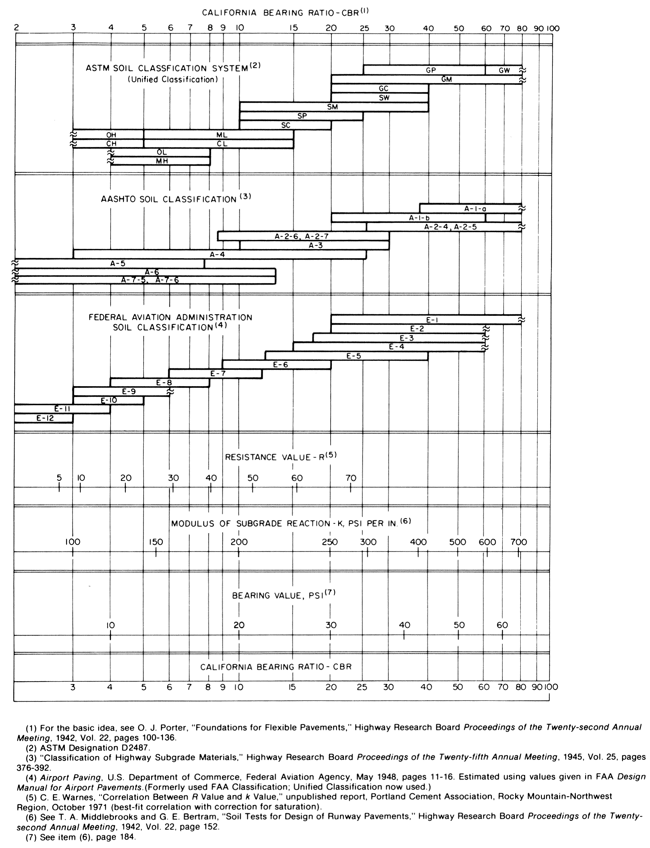
AASHTO 1993
AASHTO 1993 relates k to the subgrade resilient modulus MR through a theoretical relationship for a 30 in. (760 mm) plate (12):
with MR commonly estimated from CBR using the Heukelom and Klomp correlation (16):
Both equations appear in ACI 360R-10 Section 4.4.3. Equation 2 was intended for fine-grained soils with a soaked CBR of 10 or less, and NCHRP 1-37A recommended against its use (17, 18). For a CBR of 3, the pair gives 232 psi/in. (63 MPa/m) as a dynamic value, or 116 psi/in. (31 MPa/m) static. ACI 360R-10 cautions that the AASHTO relationships "can yield unrealistically high values" and recommends checking them against the nomograph (4), which returns the question to the 1942 chart.
ACPA
The author was part of the ACPA team that updated StreetPave for newer operating systems. The team adopted a more current CBR to MR correlation from NCHRP (17):
Dividing that MR by 19.4 produced k-values that practitioners considered too high, because expectations were anchored to the nomograph. The author therefore fit the MR to k step so that the net result returned to the nomograph's anchor points (9):
The result is about 100 psi/in. (27 MPa/m) at a CBR of 3, 200 at 10, and 250 at 20. It is used in StreetPave12, PavementDesigner.org, and ACPA's k-value tools. It was a reasonable decision at the time, and it also carried the 1942 approximation forward into a new generation of software. That is part of the reason for this paper.
"Standard Practice"
The consequence is visible in geotechnical reports. A large share of reports for pavements and floors in the United States state that the subgrade is assumed to have a CBR of 3 and therefore a k-value of 100 psi/in. (27 MPa/m). The author has not found a geotechnical text that is the source of that statement; it comes from the concrete industry's own nomographs. A geotechnical engineer assuming a low CBR may believe it conservative, but the concrete industry's correlation sets the k-value. Soils vary from site to site by any measure (a 1931 USDA soil map makes the point at a national scale), and a single assumed value for all sites is equivalent to assuming every warehouse has the same rack loads.
Elastic Layered Approach
The pavements.design k-value calculator (19) estimates subgrade MR from CBR with the Pavement ME correlation (18):
and recommends laboratory resilient modulus testing (ASTM D3999) above a CBR of 20. Layers above the subgrade are combined into a thickness-weighted equivalent modulus following Burmister (20) and Odemark (21). The center deflection under a 15 in. (380 mm) radius uniform load follows Palmer and Barber (22), and a rigid-plate correction reduces that deflection to 78.53% of the flexible-plate value (23). For a uniform half-space, the result is
Cañas Silva (24), in thesis work supervised by Covarrubias, calibrated this closed form against Pavement ME backcalculation and compared it with PCA and FAA plate load data. Covarrubias and colleagues (31) document the same subgrade model, and the relationship between static, dynamic, and effective dynamic k, in mechanistic design of concrete pavements; the calibration is applied as a factor f developed by Rodden and Covarrubias (19). The calculator reports the dynamic k-value as f times Equation 6 and the static value as half the dynamic value. For a subgrade with no base layers, f is about 0.51. The method is not new: the progression from Burmister to Palmer and Barber to Ullidtz to Cañas Silva spans 70 years. It has seen little use in the United States, possibly because the calibration work was published in Spanish and in metric units.
The calculator's documentation lists its limitations, including linear isotropic layers, the uncertainty of CBR-based MR, spatial variability, the use of a lower-bound value where support varies, and the exclusion of consolidation of cohesive soils under heavy sustained loads (19). For base layers, it agreed on average with the ACPA composite values for unstabilized subbases and ran 10% to 30% below them for stabilized layers. These are the equations built into SLABS for its dynamic and static k-values.
Comparison
Figure 2 and Table 1 compare static k-values from the three routes. The AASHTO route diverges upward as CBR increases. The ACPA route follows the nomograph. The elastic route's dynamic value sits between the two at low CBR, and its static value sits below both.
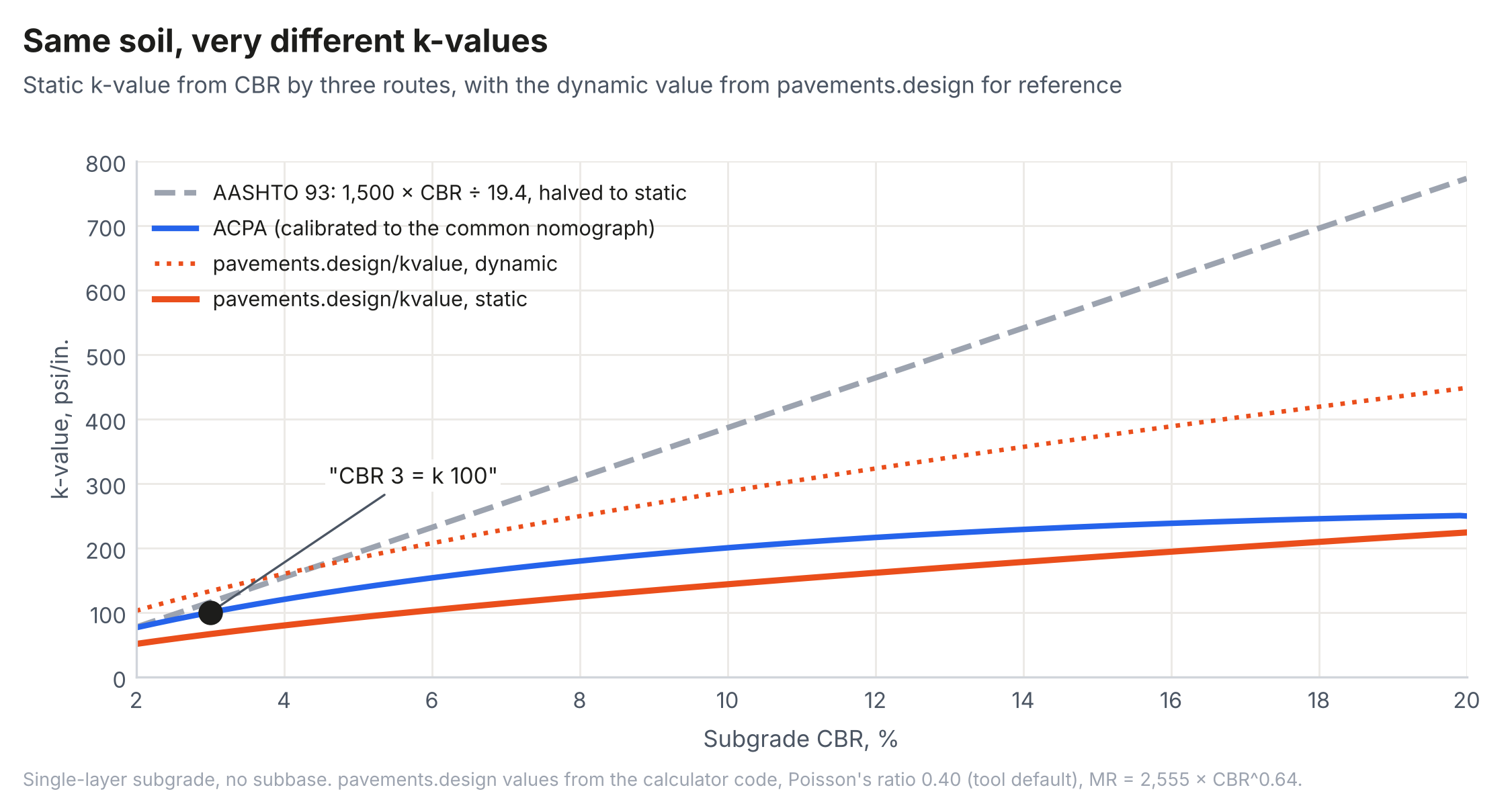
Table 1. k-Value (psi/in.) from CBR by Route
| CBR | AASHTO 1993 static | ACPA static | pavements.design dynamic | pavements.design static |
|---|---|---|---|---|
| 3 | 116 | 100 | 133 | 67 |
| 5 | 193 | 138 | 185 | 92 |
| 10 | 387 | 200 | 288 | 144 |
| 20 | 773 | 250 | 448 | 224 |
Note: pavements.design values computed with the calculator's default subgrade Poisson's ratio of 0.40.
Against the elastic route, "CBR 3 = k 100 psi/in. (27 MPa/m)" is neither the static nor the dynamic value. It is too low for a lift truck and too high for a rack.
The SSI Long-Term k-Value Method
Summary
Walker and Holland (7) define three values. Kp is the plate value, calculated from elastic theory for a rigid circular plate on a homogeneous half-space:
where Es is the soil elastic modulus, ν is Poisson's ratio, and R is the plate radius (15 in.). Kw is the value reduced for wide-area loading, and Kws is further reduced for long-term consolidation, approximated for clay soils by halving Es. Kw and Kws are found by matching the maximum slab stress from a Winkler model to that from a finite element model with solid soil elements, for a 6 in. (150 mm) slab with 7,000 lb (31 kN) rack posts in a 4 by 8 ft (1.2 by 2.4 m) rack layout. Table 2 reproduces their values; for the medium clay, Kws is reported as 35% of Kp. A second bulletin (8) converts a long-term settlement provided by the geotechnical engineer, under a strip load representing racking, into an equivalent k-value through a chart developed for a 7 in. (180 mm) slab and 9,000 lb (40 kN) posts.
Table 2. SSI Subgrade Reaction Values (7)
| Soil | Es, psi | ν | Kp | Kw | Kws |
|---|---|---|---|---|---|
| Soft clay | 2,000 | 0.45 | 110 | 70 | 50 |
| Medium clay | 4,800 | 0.35 | 230 | 130 | 80 |
| Hard clay | 10,600 | 0.20 | 470 | 260 | 140 |
| Sandy clay | 15,600 | 0.25 | 710 | 390 | 200 |
| Silty sand | 2,000 | 0.30 | 90 | 70 | n/a |
| Loose sand | 2,500 | 0.30 | 120 | 80 | n/a |
| Dense sand | 9,500 | 0.35 | 460 | 240 | n/a |
Points of Agreement
Several points in the SSI bulletins deserve support without qualification. They open with Terzaghi, correctly. The k-value depends on loaded area and duration. Short-term wheel loads and long-term rack and storage loads warrant separate values, consistent with ACI 360R-10 Sections 4.4.8 and 4.4.9 and with the guide's example design criteria, which list separate minimum k-values for rack and lift truck loading (4). The structural engineer should give the geotechnical engineer load intensities, loaded areas, durations, and the owner's sensitivity to cracking and settlement, and the geotechnical engineer should give values for each load case instead of one unqualified number. Thin base layers help under wheel loads and contribute little under wide-area sustained loads. Slab stress is insensitive to k, which the bulletins state and their own Fig. 3 shows: the ratio of slab moment to post load moves from about 0.36 to 0.45, about 26%, as the radius of relative stiffness changes from about 21 to 55 in. (8). For a 7 in. (180 mm) slab, that range spans k-values from roughly 630 to 13 psi/in. (170 to 3.5 MPa/m).
The method SSI used to reach Kw and Kws also deserves credit. Matching the maximum slab stress from a Winkler model to that from a finite element model with solid soil elements is the logic Ioannides and Tingle describe: "a k-value is required to design a pavement slab, but a pavement slab is necessary to backcalculate the appropriate k-value" (11). An effective k cannot normally be known until the slab has been built and tested; SSI built the slab in a virtual environment to find it. The disagreement that follows is with the starting value and with what the long-term reduction represents, not with that approach.
The Baseline Is Uncalibrated
Equation 7 is Equation 6. The SSI plate value is the same rigid-plate elastic solution that starts the pavements.design calculation, and the constant 2/(π × 15 in.) is the 0.04244 in. (1.1 mm)-1 of that closed form. The difference is calibration. Equation 7 returns only the recoverable, elastic part of the plate response for a soil modulus chosen from textbook ranges (7). ASTM D1196 and ACI 360R-10 Section 4.4.2 both require accounting for nonrecoverable deformation in a static plate test (4, 10). An uncalibrated elastic estimate is therefore closer to a dynamic value than a static one, and with textbook moduli it may exceed both.
For SSI's medium clay (Es = 4,800 psi, ν = 0.35), treating the modulus as the subgrade MR gives an ACPA static value of 116 psi/in. (31 MPa/m) and calibrated pavements.design values of 119 psi/in. (32 MPa/m) dynamic and 59 psi/in. (16 MPa/m) static (Figure 3). Because the calibration factor for a uniform subgrade is about 0.51, the calibrated dynamic value is almost exactly half of Kp, and the calibrated static value is about a quarter. SSI's reduction to Kws, described as a 65% cut, is measured from the uncalibrated baseline. Measured from a calibrated static value of 59 psi/in. (16 MPa/m), Kws of 80 psi/in. (22 MPa/m) is not a reduction at all. The earlier paper by the author and Ferrebee (9) reached a consistent conclusion by another route: the ACPA static value with a 0.65 factor (75 psi/in. [20 MPa/m] for this soil) is already conservative relative to the SSI long-term values for clays with a modulus above 2,000 psi (14 MPa).
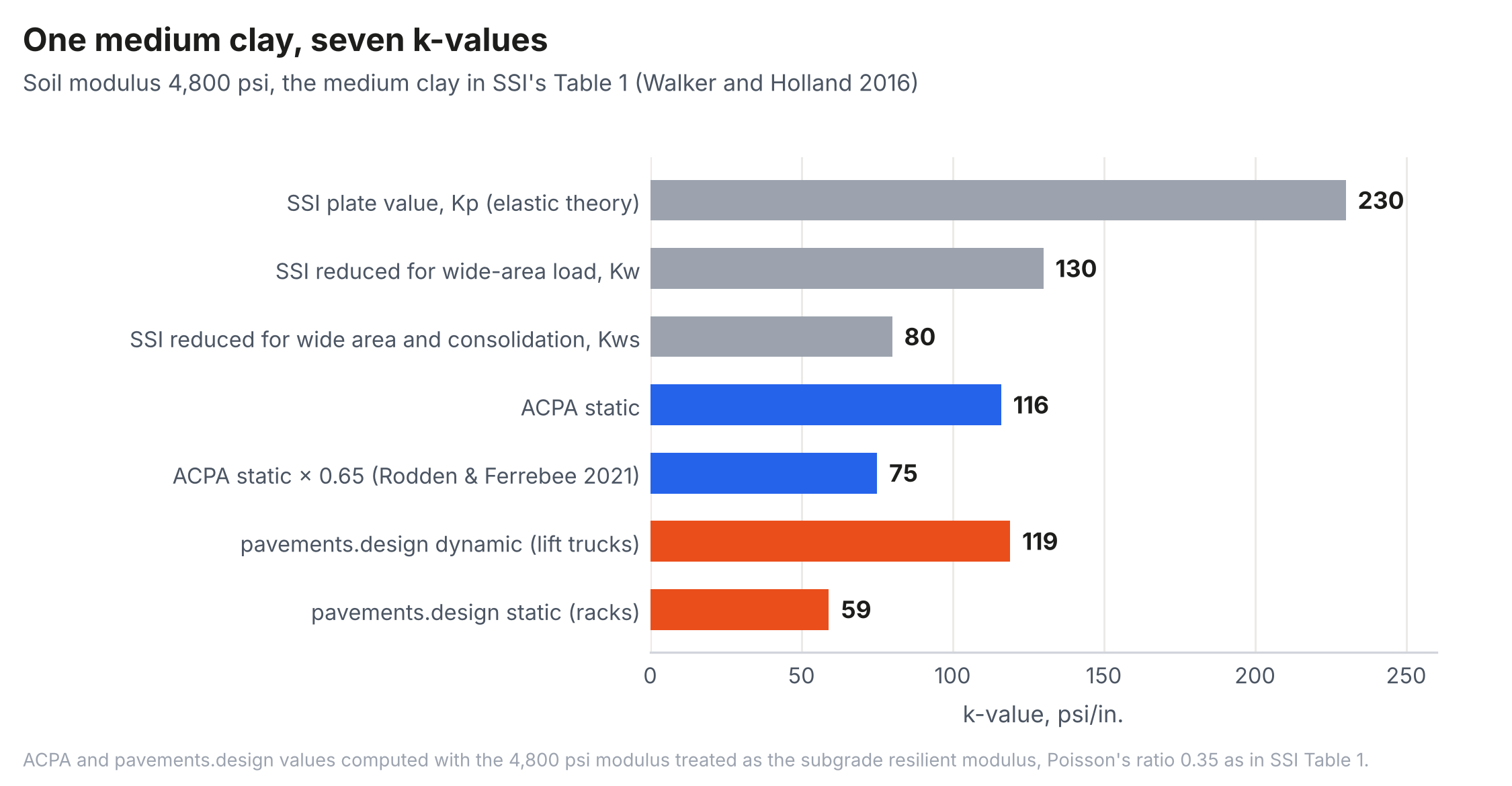
The comparison is not exact. Es in Table 2 is a static elastic modulus chosen from published ranges, and MR is a resilient modulus under repeated loading. That uncertainty cuts against the SSI baseline as much as for it: a method whose inputs vary by a factor of two or more, and whose reductions are reported to the percent, conveys more precision than it has.
Settlement Is Not Stiffness
The larger issue is what a long-term k-value represents. A value reduced to match consolidation settlement is no longer a stiffness; it is a settlement estimate expressed in the units of a spring constant, which is the use Terzaghi said the theory should not be put to (5). Three problems follow.
First, the SSI bulletins themselves show that the Winkler model cannot represent the settlement it is asked to carry. For settlement below the elevation of nearly uniform pressure, about 14 ft (4.3 m) for the modeled rack layout, "the entire slab moves down causing little influence on the differential deflections of the slab, and therefore the slab moments are not significantly affected" (7). The second bulletin notes that below about 66 psi/in. (18 MPa/m) for its rack geometry, slab settlements from the Winkler model become excessive, because the uncoupled springs cannot converge toward the nearly uniform pressure beneath a stiff slab (8). The settlement that matters to the owner is largely invisible to slab stress, and the model used to translate it into k breaks down where the settlement becomes large.
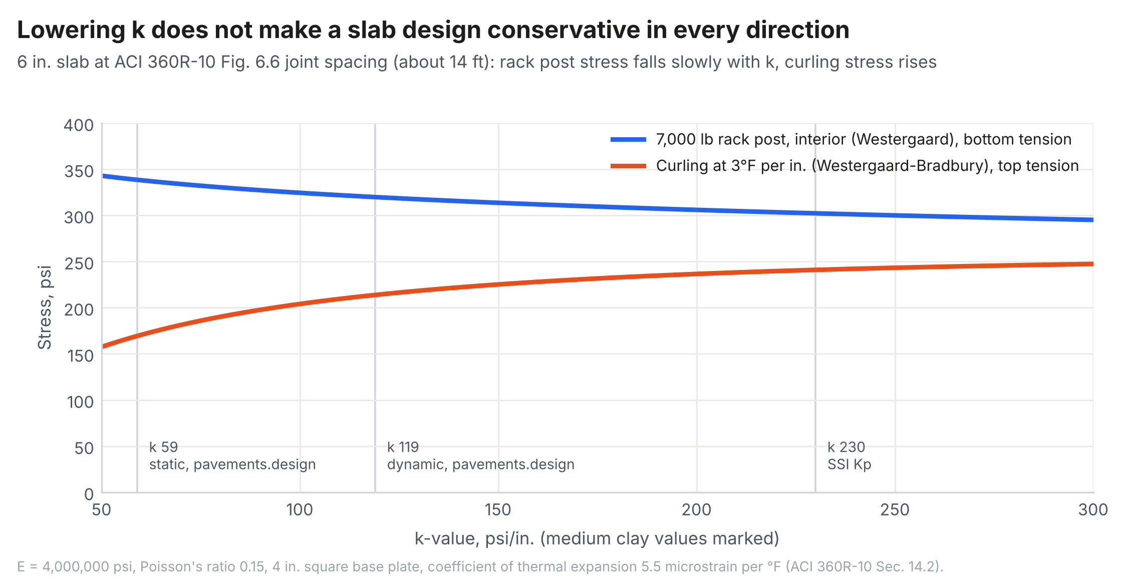
Second, a settlement-reduced k is not conservative for curling. Curling stress at mid-panel is generated by the slab's own weight acting against the support immediately beneath it, at contact pressures of about 0.5 psi (0.0034 MPa) for a 6 in. (150 mm) slab. Under the Westergaard-Bradbury solution (2, 25), a softer foundation lengthens the radius of relative stiffness and reduces the computed curling stress. Figure 4 shows a 6 in. (150 mm) slab at the Fig. 6.6 joint spacing of ACI 360R-10 (about 14 ft) with a 3°F per in. (1.7°C per 25 mm) gradient. Between k = 59 and 230 psi/in. (16 and 62 MPa/m), the interior stress from a 7,000 lb (31 kN) rack post on a 4 in. (100 mm) base plate falls by about 11%, from 339 to 302 psi (2.3 to 2.1 MPa), while the curling stress rises by about 43%, from 169 to 241 psi (1.2 to 1.7 MPa). A value reduced for consolidation many feet down understates the curl produced by the near-surface support. The SLABS software developed by the author's company checks top-down cracking with the slab curled and bottom-up cracking with the slab flat on the same k-value, so that curl does not put the bottom fiber in compression and mask load stress. A settlement-based k in the curled analysis would defeat that conservatism. Curl and load also interact through loss of contact, so adding a curling stress to a load stress is itself an approximation (26); the direction of the error from an artificially low k does not change.
Third, the long-term k leads to thicker slabs, and thicker slabs do not reduce settlement. Using Terzaghi's equivalent circular footing (5), the author compared a 7 in. (180 mm) slab on k = 100 psi/in. (27 MPa/m) with a 9 in. (230 mm) slab on an arbitrarily reduced k = 50 psi/in. (14 MPa/m), each carrying a 10,000 lb (44 kN) load (27). The thicker slab spreads the load over a larger equivalent footing, with a radius of 118 in. (3,000 mm) compared with 82 in. (2,080 mm), but the predicted average settlement of the two cases is within 3%. Thickening by almost 30% bought essentially no reduction in settlement. It does add load: each 2 in. (50 mm) of concrete adds 25 psf (1.2 kPa) of sustained pressure, about 4% of the 500 psf (24 kPa) strip load SSI uses to represent racking plus 87.5 psf (4.2 kPa) of 7 in. (180 mm) slab. And for the same differential settlement, a thicker slab opens joints and cracks wider at the surface. ACI 360R-10 Section 5.9 also warns that including "cumulative factors of safety in the modulus of subgrade reaction, applied loads, compressive or flexural strength of the concrete, or number of load repetitions, may produce a very conservative and, consequently, expensive construction," and that the factor of safety "is normally accounted for only in the allowable flexural stress" (4). A settlement-reduced k combined with the usual factor of safety on concrete stress is the compounding the guide describes.
How the Guide Got Here
ACI 360R-92 contained a worked plate load example with numbers, giving a k of about 180 psi/in. (49 MPa/m), and a scope statement: "consolidation of the subgrade is beyond the scope of this report" (28). ACI 360R-06 and 360R-10 removed that statement, replaced the worked example with a unitless sketch showing two different k-values for one test, and added Section 4.4.8, which states that settlement under heavy distributed loads "typically indicates an equivalent k value of only 20 to 30% of that measured by a plate load test" (4). No reference is given for the 20 to 30%. Read together, the changes invite designers to reduce k for settlement, which is the practice this paper argues against, and they move a geotechnical question into a concrete design guide without the tools to answer it.
Sensitivity
ACI 360R-10 Section 4.5.2 states that "the slab thickness calculation is insensitive to small changes in k, therefore the exact k value need not be known." For load stress, Figure 4 and the SSI moment ratio both bear this out. The statement is a reason that a defensible estimate is sufficient, not permission to use any value. Two qualifications apply. When the design includes curling, the sensitivity reverses direction and grows: curling stress is more sensitive to k than load stress over the practical range. And k-values used to justify thinner slabs through high composite support raise the same issue from the other side. ACI 360R-10 Section 14.13 calls it an "anomaly" that the methods permit thinner slabs as k increases, because stiffer support increases curling (4), and AASHTOWare Pavement ME predicts increased required thickness above about 300 psi/in. (81 MPa/m) for jointed plain concrete pavement (29). Early plate load research also found that an 18 in. (460 mm) subbase with a CBR of 100 did not change the foundation modulus measured beneath it (11). A subbase is for erosion resistance and uniformity of support, not for raising k so the slab can be made thinner.
Responsibility
The SSI bulletins describe responsibility for k as shared between the structural and geotechnical engineers (7). This paper agrees on the information exchange but proposes a cleaner division of the deliverables.
The slab designer is responsible for the static and dynamic k-values: the stiffness of the subgrade and base layers under sustained and transient loads, from testing or a calibrated method, with an understanding of the design's sensitivity to them. In SLABS, the dynamic k-value from the elastic layered method is applied to lift truck loads and the static value to rack loads, with engineer override of either.
The geotechnical engineer is responsible for long-term settlement: total and differential settlement under the actual rack layout and storage loads, time-dependent soil behavior, and the investigation needed to support those predictions. If predicted settlement is within what the owner and racking can tolerate, the slab is designed on its static and dynamic k-values. If it is not, the remedy belongs to the ground (removal and replacement, surcharging, preloading, or ground improvement) or to a structural slab designed under ACI 318 (9, 14). Thickening a slab-on-ground is not a remedy for consolidation settlement.
That division matters for liability as much as for performance. A reduced long-term k-value transfers settlement risk from the geotechnical engineer to the slab designer without transferring control over the soil or the tools to evaluate it. Geotechnical scopes have contracted under price competition, with boring spacing on building sites increasing over recent decades (30), and an unqualified correlated k-value can make a sparse investigation appear complete. ACI 360R-10 Section 4.4.7 states that "the importance of providing uniform support cannot be overemphasized." Uniform support comes from site investigation and earthwork, not from a lower number in a thickness calculation.
Recommendations
- Report and design with two k-values: a dynamic value for moving loads and a static value for sustained loads, each with its basis stated.
- Estimate k from a calibrated method. Of the methods reviewed, the elastic layered approach of pavements.design is the most defensible because it treats layers explicitly, separates dynamic and static values, and documents its limitations. The ACPA relationship remains a reasonable static estimate. Equation 1 with Equation 2 should not be used.
- Do not use a k-value reduced for long-term settlement in curling analysis. If a reduced k is used for rack load stress, the curling analysis should still use the static k of the near-surface support.
- Require the geotechnical engineer to evaluate long-term settlement for the actual storage layout and to recommend ground treatment where it is not tolerable, rather than providing a reduced k-value that shifts the problem to the slab.
- Remove "CBR 3 = k 100 psi/in. (27 MPa/m)" and similar unqualified correlations from geotechnical report templates and from concrete design guidance, and restore an explicit statement that consolidation of the subgrade is outside the scope of slab thickness design.
Conclusions
The k-value is a stiffness that depends on load size and duration, and its originators said so. The correlations in common use differ widely for the same soil, and the most repeated value, 100 psi/in. (27 MPa/m) for a CBR of 3, is a 1942 flexible pavement approximation that matches neither the calibrated static nor the calibrated dynamic value from an elastic layered analysis. The SSI long-term method correctly identifies the dependence of k on loaded area and time and the need for separate wheel and rack values, but it measures its reductions from an uncalibrated elastic baseline and folds settlement into a parameter the slab analysis uses for stiffness. The result understates curling, invites slab thickening that does not reduce settlement, and compounds conservatism that ACI 360R-10 cautions against. Slab designers should own static and dynamic stiffness. Geotechnical engineers should own long-term settlement.
References
1.Westergaard, H. M. Stresses in Concrete Pavements Computed by Theoretical Analysis. Public Roads, Vol. 7, No. 2, 1926, pp. 25-35.
2.Westergaard, H. M. Analysis of Stresses in Concrete Roads Caused by Variations of Temperature. Public Roads, Vol. 8, No. 3, 1927, pp. 54-60.
3.Winkler, E. Die Lehre von der Elasticität und Festigkeit. Prague, 1867.
4.ACI Committee 360. Guide to Design of Slabs-on-Ground. ACI 360R-10. American Concrete Institute, Farmington Hills, Mich., 2010.
5.Terzaghi, K. Evaluation of Coefficients of Subgrade Reaction. Géotechnique, Vol. 5, No. 4, 1955, pp. 297-326.
6.Packard, R. G. Slab Thickness Design for Industrial Concrete Floors on Grade. IS195. Portland Cement Association, Skokie, Ill., 1976.
7.Walker, W. W., and J. A. Holland. Modulus of Subgrade Reaction - Which One Should be Used? Engineering Bulletin. Structural Services, Inc., 2016.
8.Walker, W. W., and J. A. Holland. Modulus of Subgrade Reaction for Storage Racking on Slabs-on-Ground Made Easy. Engineering Bulletin. Structural Services, Inc.
9.Rodden, R., and E. Ferrebee. Analysis and Evaluation of the Development of Various k-Values for Use in Design. Proceedings, 12th International Conference on Concrete Pavements, 2021, pp. 90-97. https://doi.org/10.33593/8su5wzp1.
10.ASTM D1196. Standard Test Method for Nonrepetitive Static Plate Load Tests of Soils and Flexible Pavement Components, for Use in Evaluation and Design of Airport and Highway Pavements. ASTM International, West Conshohocken, Pa.
11.Ioannides, A. M., and J. S. Tingle. Secrets of the Plate Load Test (1941-1955).
12.AASHTO. Guide for Design of Pavement Structures. American Association of State Highway and Transportation Officials, Washington, D.C., 1993.
13.FHWA. Using Falling Weight Deflectometer Data with Mechanistic-Empirical Design and Analysis. FHWA-HRT-16-011. Federal Highway Administration, 2017.
14.Anyang, M. Y., B. D. Atarigiya, R. Ofori-Addo, and N. K. Allotey. Plate Load Test: Getting It Right. 49th GhIE Annual Conference, 2018.
15.Middlebrooks, T. A., and G. E. Bertram. Soil Tests for Design of Runway Pavements. Proceedings, Highway Research Board, Vol. 22, 1942.
16.Heukelom, W., and A. J. G. Klomp. Dynamic Testing as a Means of Controlling Pavements During and After Construction. Proceedings, International Conference on the Structural Design of Asphalt Pavements, 1962.
17.NCHRP. Guide for Mechanistic-Empirical Design of New and Rehabilitated Pavement Structures, Appendix CC-1: Correlation of CBR Values with Soil Index Properties. National Cooperative Highway Research Program, 2001.
18.FHWA. Geotechnical Aspects of Pavements Reference Manual. NHI-05-037. Federal Highway Administration, 2006.
19.pavements.design. k-Value Calculator: About, Equations, Comparison, and Limitations. https://pavements.design/kvalue. Accessed October 2026.
20.Burmister, D. M. The General Theory of Stresses and Displacements in Layered Soil Systems. Journal of Applied Physics, Vol. 16, 1945.
21.Odemark, N. Investigations as to the Elastic Properties of Soils and Design of Pavements According to the Theory of Elasticity. Statens Väginstitut, Stockholm, 1949.
22.Palmer, L. A., and E. S. Barber. Soil Displacement Under a Circular Loaded Area. Proceedings, Highway Research Board, Vol. 20, 1940.
23.Ullidtz, P. Pavement Analysis. Elsevier, Amsterdam, 1987.
24.Cañas Silva, J. T. Método de Cálculo del Módulo de Reacción "K" para un Sistema de Fundación Multicapas para Pavimentos de Hormigón. Memoria de Título, Ingeniería Civil en Obras Civiles, Universidad de Los Andes, Santiago, 2010. Supervisor: J. P. Covarrubias Vidal.
25.Bradbury, R. D. Reinforced Concrete Pavements. Wire Reinforcement Institute, Washington, D.C., 1938.
26.Face, A., and N. Parkes. Addressing Concrete Slab Curl Numbers. ForConstructionPros, 2026.
27.Rodden, R. Terzaghi Post 2: A Much Thicker Slab Because of a Lower Assumed k-Value Does Not Reduce Soil Settlement to the Degree People Often Think. LinkedIn, 2025.
28.ACI Committee 360. Design of Slabs on Grade. ACI 360R-92. American Concrete Institute, Detroit, Mich., 1992.
29.Rodden, R., G. Voigt, and L. Wathne. Comparison of Roadway Jointed Plain Concrete Pavement (JPCP) Thickness Design Methods Common in the United States. Proceedings, 12th International Symposium on Concrete Roads, 2014.
30.Parkhill, T. Common Misunderstandings with Geotechnical Work. STRUCTURE, December 2016.
31.Covarrubias Vidal, J. P., et al. Modeling of Subgrade for Thin Concrete Pavement. Technical Paper. TCPavements, 2020.
Related in This Series
- Article on this topic: Stop Asking the Slab to Fix the Soil
Where 'CBR 3 = k 100 psi/in.' came from, why a settlement-reduced k-value isn't a stiffness, and who should own long-term settlement.
- The Thickness Methods of ACI 360R-10 and Their PCA Lineage
Traces how PCA added a joint factor in 2001 and 2008 that ACI 360R-10's thickness procedure still omits.
- Joint Spacing, Curling, and the Factor of Safety in ACI 360R-10
Checks the Fig. 6.6 joint spacing and the Table 5.2 factor of safety against the guide's own curling and fatigue data.
- Raised but Not Resolved: An Audit of ACI 360R-10
Audits eight design decisions in ACI 360R-10 for whether each issue raised is carried through to a design method.
- Joint Load Transfer and Slab Thickness for Speculative Warehouse Floors
Mechanistic-empirical design and contractor cost survey for one spec warehouse with three joint details.
Revision history
- November 4, 2026: Added metric units to k-values.
- November 3, 2026: Completed references; added metric units and links to other pieces in the series.
- October 27, 2026: First published on slabs.design/knowledge.
To cite this paper, use the citation printed in the PDF. It includes the revision date, so readers can match your citation to the text you read.