Technical Paper|TSD-11TP
Similar Inputs, Different Problem: PCA's Airport Pavement Method on Industrial Floors
The Slab Designer, LLC | Published November 3, 2026 | Revised November 4, 2026
Abstract
For five decades, engineers designing heavy industrial floors and port pavements have borrowed the Portland Cement Association's airport method, Packard's Design of Concrete Airport Pavement (EB050, 1973) and its PDILB computer program, later carried forward in PCA's AIRPORT program and the American Concrete Pavement Association's AirPave. The attraction is the inputs: any wheel layout, contact area, and tire pressure, where the floor charts offer a few fixed configurations. This paper rebuilds the method from its source equations, validates it against the computer output and design examples Packard printed, and validates the companion floor method (EB075, 2008) against an example from that guide. The rebuilt PDILB engine reproduces Packard's thirteen printed Boeing 727 stresses within 0.13% and his DC-8 wheel-by-wheel moments to the fourth decimal once PDILB's 20-sector integration is copied; it also finds a C-5A case where PDILB's search appears to have stopped 3.8% short of the true maximum. Having inputs in common does not make the airport method an industrial design basis. EB050 sizes an infinitely large, fully supported slab for a load at the slab interior and assumes adequate load transfer at every interior joint, with safety factors and fatigue relationships calibrated to airfield traffic and airfield distress. Industrial floors fail by other mechanisms: curl and loss of support at joints, several load groups on one panel, small hard wheels that bear like short line loads rather than tire footprints, and spalling from small, hard wheels striking a deflected joint edge, a mechanism airfields carrying only pneumatic tires do not see. For one dual-wheel container handler, moving the load from the slab interior to an interior joint or a free edge alone moves the required thickness from 9.5 in. to 11.5 in. or 14.0 in. before curl is considered. The method has served industrial owners with a high but unknown factor of safety. Both PCA bulletins were written as stepping stones and revised several times; the 1955 airport edition offered its method as safe "until the application of the elastic solid theory is developed" and required thicker edges where load transfer was missing. Consensus design guidance for floors stopped moving at about the time finite element and mechanistic-empirical methods made the next step practical.
Keywords: EB050, PDILB, AirPave, airport pavement design, industrial floor design, Westergaard, Pickett influence chart, interior load, joint factor, fatigue, differential deflection, mechanistic-empirical
Introduction
Ask a room of engineers how they size a slab for a 100,000 lb container handler and a good number will say "AirPave," or, if they have been at it long enough, "the PCA airport program." The answer makes sense. The floor method of the time, PCA's Slab Thickness Design for Industrial Concrete Floors on Grade (Packard, 1976) and its successors in Concrete Floors on Ground (EB075), provides charts for single and dual lift truck axles, rack posts, and distributed loads. Equipment that falls outside those configurations, such as straddle carriers, top-picks, and multi-axle transporters, has nowhere to go. The airport method takes any wheel coordinates, any contact area, and any tire pressure, and returns a maximum stress.
The author has a stake in this. While at ACPA, the author wrote the user's manual for AirPave, the Windows version of PCA's airport program, and that manual includes a dump truck in its discussion of non-aircraft loads. Flexible inputs were presented as a feature, and they are one. This paper asks the question the manual did not: when a method accepts the inputs, does it also fit the problem?
The paper has four parts: the background and basis of the airport method, a validation of a rebuilt version against the printed output in both PCA guides, a comparison of the performance criteria and distress mechanisms of airfields and industrial floors, and the limitations that make the factor of safety of an airport-method floor high but unknown.
Background: Two Bulletins From One Author
Robert G. Packard spent four decades at PCA and ACPA and wrote the design procedures most of the concrete pavement industry still recognizes: the airport method (1973), the industrial floor charts (1976), and the highway and street method (1984). The airport and floor methods share a root. Both use Westergaard's interior solution for a slab on a dense-liquid foundation (Westergaard, 1926), as generalized by Pickett and others at Kansas State into a closed-form expression for the moment under a load of any shape (Pickett et al., 1951) and drawn by Pickett and Ray as influence charts (1951).
The airport method predates the computer. PCA first published Design of Concrete Airport Pavement in 1950 and revised it five years later. The 1955 edition (EB050.02P) was built on Pickett and Ray's influence charts: simplified design charts for single, dual, and dual-tandem gear were produced by counting blocks on large versions of the moment chart, and the charts were offered directly for "any number of tires with any arrangement and with any tire pressure or contact area." The flexibility that industrial engineers value was there from the start.
EB050 lays out the method plainly: "The flexural stresses used in the design procedure are those at the interior of a slab, assuming that the load is applied at some distance from any free edge of a slab." It explains why that is acceptable for airfields: "When the slab edges at all joints (longitudinal and transverse) are provided with adequate load transfer, it has been found that a paved area acts as a continuous large slab." The interior assumption was a deliberate engineering judgment, tied to a stated condition at the joints. The 1955 edition is even more direct. Thickness from the charts "is theoretically correct when a load is located in the interior of a slab," and Pickett and Ray's charts for loads at or near an edge were set aside on purpose: "Since free outside edges are not a critical location in airport pavements, and since adequate load transfer is provided at all interior joints, the influence charts for a free edge or near an edge were not used." Where load transfer could not be provided, both editions changed the joint, not the stress. In 1955, the outside edges of fillets, where pilots cut corners and channelize traffic near the edge, got "an additional 20 per cent thickness," and undoweled expansion joints at intersections were thickened as well. In 1973, "where no load transfer mechanism is provided, the joint edges subject to traffic are thickened," and the undoweled expansion joint detail thickens both edges 20 percent. Because stress varies roughly with the inverse square of thickness, a 20% thickened edge is worth about 1.22 = 1.44 in stress, the same range as PCA's later floor joint factor of 1.4 to 1.6.
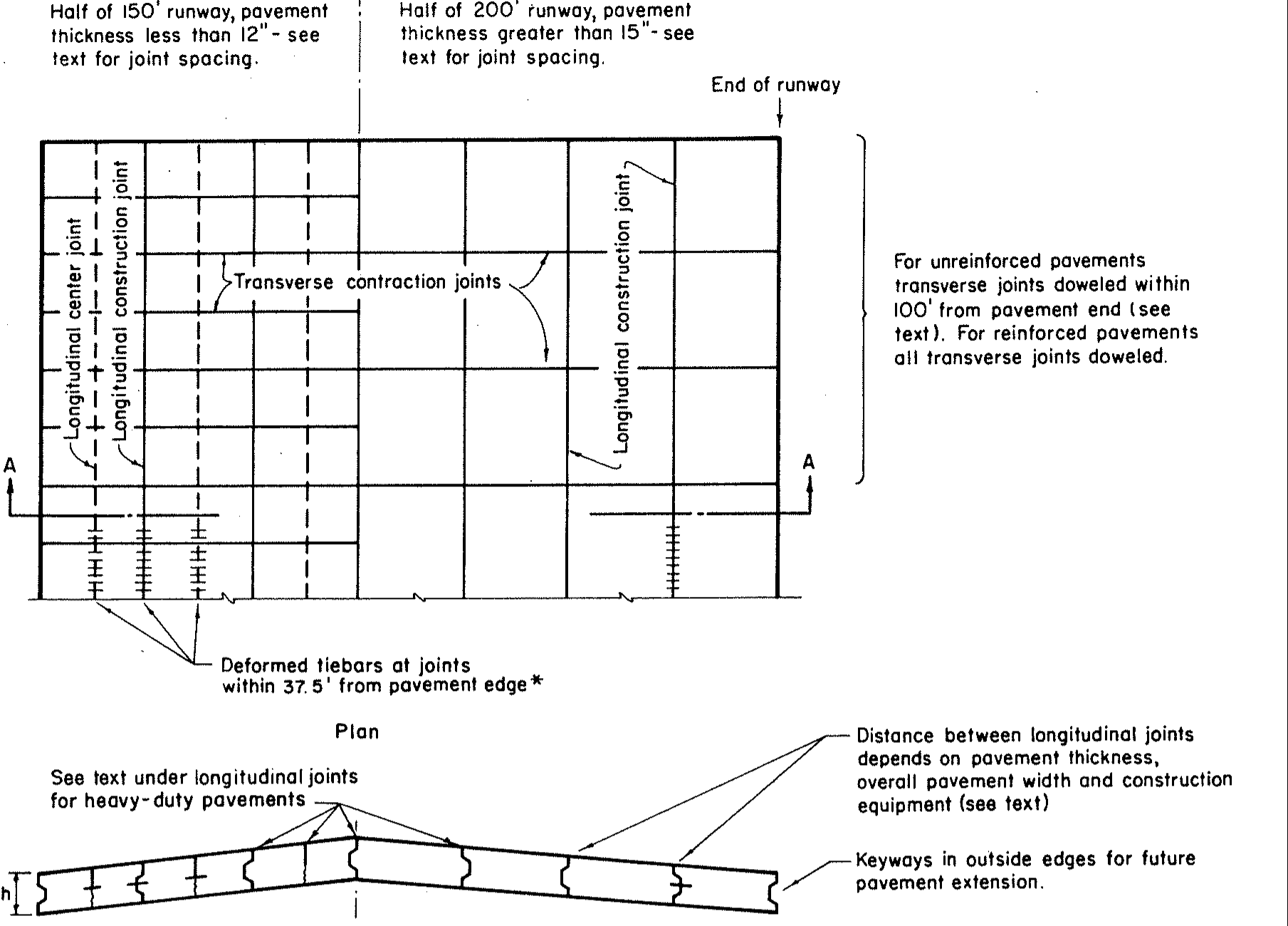
The airfield reasoning deserves a careful reading. "Free outside edges are not a critical location" does not mean that airfield edges and joints are unimportant; cracking can initiate there as it does in floors. It means that an airfield has no free edges in traffic: aircraft do not run off the paved area, so every joint a wheel crosses is an interior joint. The second premise, adequate load transfer at all interior joints, describes the system more than the joint. Many airfield joints are not doweled; a common arrangement dowels, keys, or ties longitudinal joints and leaves transverse contraction joints undoweled; PCA's 1973 jointing plan doweled unreinforced transverse joints only within 100 ft (30 m) of the pavement end (1). Panels are large, because fewer joints were the goal, and larger panels require thicker slabs (22). Airfield pavements are also frequently built on stabilized layers, in some cases a lean concrete base over a granular layer under the pavement, and that support limits deflection across the whole system, which appears as load transfer when joints are tested. Airfield design practice, in short, treated the free edge as the critical case and interior joints, with or without dowels, as sufficient, in large part because of the support beneath them. A warehouse floor on a granular base with sawcut joints and curled panels does not share that premise.
PDILB, the computer program that replaced hand counting on the influence charts, was published by Packard in 1967. It integrates the Kansas State moment expression over each tire imprint, sums the contributions of every wheel within three radii of relative stiffness, and moves and rotates the gear until the moment is largest. The program was converted to microcomputers as PCA's AIRPORT (MC006), adopted by the International Civil Aviation Organization in 1981 as the single method for evaluating aircraft loads on concrete pavements under the ACN system, and later converted to AirPave by ACPA, which added a joint factor and a free-edge factor. Its latest version, AirPave 11, dates from 2011.
The Model
For a point load P at distance r and angle φ from the point of interest, the bending moment in direction ψ in an infinite plate on a dense liquid is
where x = r/ℓ, ker and kei are Kelvin functions of order zero, μ is Poisson's ratio, and ℓ is the radius of relative stiffness,
with E the concrete modulus, h the slab thickness, and k the modulus of subgrade reaction. Integrating Equation 1 over each tire imprint and summing over the wheels gives the moment per unit contact pressure, which PDILB reports as F, and the stress
with q the contact pressure. The imprint is an ellipse with the length and area of PCA's rounded rectangle (width 0.6 of the length), so that W = 0.6655 L for the ellipse. EB050 uses E = 4,000,000 psi and μ = 0.15.
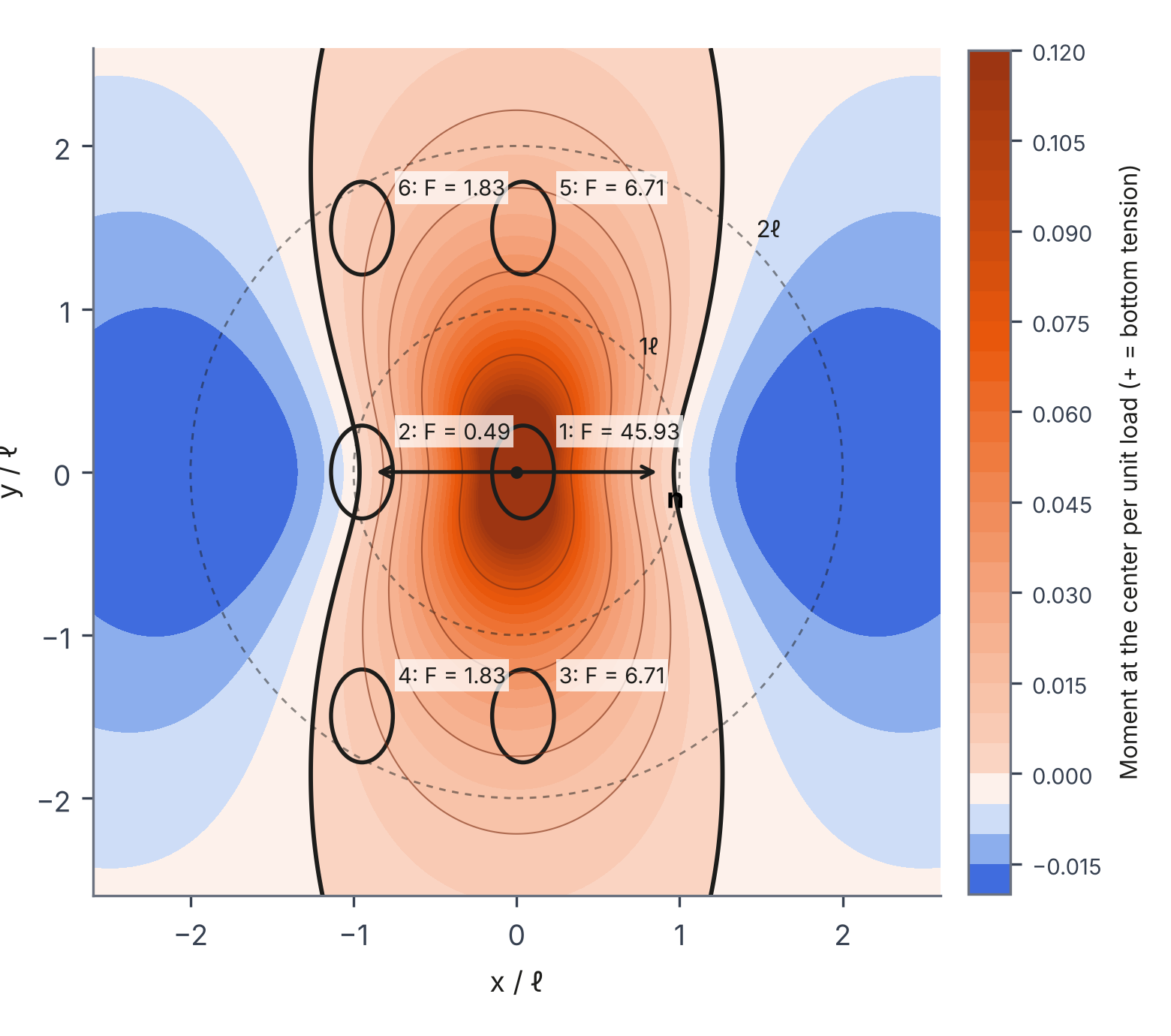
Figure 2 draws Equation 1 as a surface for the Lockheed L-2000 of EB050's Example 2, with the gear placed where the moment is largest. A load on the orange area adds tension at the bottom of the slab at the marked point; a load on the blue area reduces it. The dual wheel sits almost exactly on the zero line, which is why PDILB's printout gives it F = 0.4991 against 45.9 for the wheel at the point.
EB050 turns stress into thickness two ways. Chapter 2 divides the modulus of rupture by a safety factor: 1.7 to 2.0 for aprons, taxiways, runway ends, and hangar floors, and 1.4 to 1.7 for the central portion of runways. Appendix A replaces the safety factor with a fatigue analysis: a design modulus of rupture reduced for strength variability, Table A4 relating stress ratio to allowable repetitions, Miner's hypothesis for mixed traffic, and load repetition factors that account for how aircraft wander across a taxiway or runway.
Validation
The Slab Designer rebuilt the method from Equations 1 to 3 in a free tool, PCA Airport Thickness Design (slabs.design/pca-airport), and a companion, PCA Slab Thickness Design (slabs.design/pca), digitizes the 2008 floor charts. The question for any rebuild is whether it gives the answers the source printed. EB050 is unusually good for this, because Packard printed actual PDILB output in Appendix C.
Figure 2a compares the thirteen maximum stresses PDILB printed for the Boeing 727 in Example 1 with the rebuilt engine; the largest difference is 0.13%. Table 1 summarizes the remaining checks.
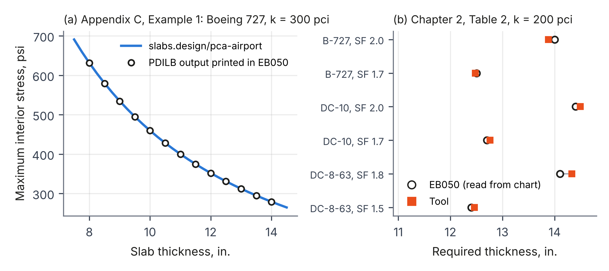
Table 1. Printed values in both PCA guides and the rebuilt methods.
| Guide and example | Printed | Rebuilt | Note |
|---|---|---|---|
| EB050, App. C, Ex. 1, B-727, 8 to 14 in. | 631.2 to 278.8 psi | 631.4 to 278.9 psi | largest difference 0.13% |
| EB050, App. C, Ex. 2, L-2000, 12 in. | 431.8 psi | 431.4 psi | angle 90.0 deg in both |
| EB050, App. C, Ex. 3, C-5A, ℓ = 50 in. | F = 60.5385 | F = 60.4891 | 0.08% |
| EB050, App. C, Ex. 4, DC-8, three angles | F = 54.8739 / 54.9394 / 54.8666 | 54.8740 / 54.9396 / 54.8668 | with PDILB's 20 sectors |
| EB050, Ch. 2, Table 2, six designs | 12.4 to 14.4 in. | within −0.12 to +0.23 in. | PCA read these from charts |
| EB050, App. A, Table A3, mixed traffic | 82.8% | 82.8% | stress ratio rounded, as PCA did |
| EB075 (2008), Fig. 5-6b, Lift Truck B | F = 0.775 at 10 in. | 0.776 | dual-wheel factor |
| EB075 (2008), metric Lift Truck A, free edge | 235 mm | 235 mm | Fig. 5-5b |
| EB075 (2008), Table 5-3b, 5 in., k 50, MR 550 | 535 psf | 535 psf | distributed load |
Three details from the validation are worth recording. First, the remote-wheel moments in Example 4 come out about 0.4% low with exact integration and match to the fourth decimal when each remote imprint is split into exactly 20 equal sectors, as PDILB did; 19 or 21 sectors miss. Second, PDILB appears to have searched for the maximum by climbing from wheel 1. For the C-5A at ℓ = 30 in., the printout reports F = 38.867 near wheel 1, which the rebuilt engine reproduces by searching the same way (38.876), but the true maximum is near the outer wheels and 3.8% higher. Third, ACPA's AirPave stored three runs of its own in its database (Airbus A300 variants at 15 in., k = 200 pci [54 MPa/m]); the rebuilt engine matches them within 0.06%. AirPave did not keep Table A4 as printed, either. Its allowable repetitions follow a straight line in log N between the table's end points, which reproduces its saved outputs to within 0.05%.
For the floor method, the 2008 examples solve within chart-reading precision except one, which was discussed in an earlier paper in this series (16): the inch-pound Lift Truck A prints 9.25 in. for the free edge, the same as the metric example's 235 mm, and appears to have been carried over from the metric problem.
The methods, then, are what PCA said they were. What follows is about whether they fit the problem they are now asked to solve.
Similar Inputs Are Not a Design Basis
A design method is more than a stress calculation. It is a stress calculation tied to a performance criterion that was calibrated against the distress the method was meant to prevent. EB050's safety factors and Table A4 were calibrated against airfield pavements: slabs carrying wandering aircraft on pneumatic tires, with no free edges in traffic and frequently stabilized support beneath the joints, in the open air. Moving the stress calculation to a warehouse moves none of that calibration with it.
Different Criteria
The floor guidance has its own criteria. ACI 360R-10 ties floor thickness to a fatigue relationship between stress ratio and load repetitions of the kind PCA publishes for lift trucks, and it suggests limits on differential deflection across joints: about 0.010 in. for small, hard wheels and 0.020 in. for larger, cushioned or rubber wheels, with 0.060 in. described as an upper limit beyond which joints are unstable. Those deflection limits exist because of how industrial joints fail. EB050 has no deflection criterion, and an interior-load model cannot produce a joint deflection to check.
The fatigue curves differ as well. Table 2 sets EB050's Table A4 beside PCA's 2008 floor fatigue table at the same stress ratios.
Table 2. Allowable load repetitions by stress ratio in PCA's airport and floor methods.
| Stress ratio | EB050 (1973), Table A4 | EB075 (2008), Table 5-1 |
|---|---|---|
| 0.45 | unlimited | 62,790,761 |
| 0.50 | unlimited | 762,043 |
| 0.51 | 400,000 | 485,184 |
| 0.55 | 130,000 | 124,523 |
| 0.60 | 32,000 | 30,927 |
| 0.70 | 2,000 | 1,917 |
The curves agree closely above a stress ratio of 0.51, but EB050 treats 0.50 as an endurance limit with unlimited repetitions, where the floor table allows about 760,000. A busy distribution center can put several million lift truck passes on a cross-aisle joint over the life of the floor. Read with EB050's curve, a stress ratio of 0.50 never fatigues; read with the floor curve, it is used up.
Different Distress
The two kinds of pavement also fail differently. In the author's experience, airfield pavements tend to be thicker than flexure alone requires, often because owners prefer larger panels to reduce the length of joints, which were seen as the performance problem. The distress that drives airfield maintenance is mostly foreign object debris (spalled fragments that can be ingested by engines) and material durability, because the pavement is outdoors. Industrial floors are indoors, dry from the top only, and curl. They carry small, hard wheels whose impact on a deflected joint edge spalls it, a mechanism that is absent on airfields serving only pneumatic tires. Table 3 summarizes the contrast.
Table 3. Airfield pavements and industrial floors.
| Condition | Airfield pavement (EB050's basis) | Industrial floor |
|---|---|---|
| Tires | pneumatic, high pressure | pneumatic, cushion, and small hard (polyurethane, steel) wheels |
| Traffic | wanders; load repetition factor below 1.0 | channelized in aisles; every pass crosses the same joints |
| Joints | load transfer assumed at all joints | often sawcut and undoweled; opening with shrinkage |
| Environment | outdoors; durability and debris | indoors; one-sided drying, curl, loss of support at joints |
| Governing distress | cracking, spalls that become debris, durability | joint spalling under hard wheels, corner and edge cracking, rocking |
| Loads on a panel | gear passes | trucks, rack posts, and stored goods together |
Limitations of the Interior-Load Model
The interior-load model is the core of both PCA methods, and its limits are well documented. ACI 360R-10, Section 14.13, states that the PCA, WRI, and Corps of Engineers methods, all based on Westergaard and full support, "give erroneous results for slab thickness where the slab is not in contact with the subgrade."
The joint factor is the clearest evidence. PCA added a factor of up to 1.6 to its floor method in 2001, based on finite element analysis showing edge stresses 50% to 60% higher than interior stresses, and tied it to joint type, shrinkage, and joint spacing in 2008 (Farny and Tarr, 2008). That is PCA saying, in its own method, that an interior load does not characterize a floor with joints. The airport method said the same thing in 1955 with its 20% thickened edges, and PCA's first floor bulletin said it in 1978: it assumed a panel acts as part of a continuous slab when its joints have adequate load transfer, and called for thickening the slab 50% where lift trucks cross a free edge (Spears, 1978), reduced to 25% in the 1983 edition (Spears and Panarese, 1983). An engineer who takes a PDILB or AirPave stress into a floor design carries the interior stress across and can leave that joint requirement behind. AirPave's joint factors (1.39 for a single wheel, 1.33 dual, 1.00 single tandem, 1.14 dual tandem) are the airport method's version of the same correction, derived from a limited number of ILSL2 runs on one 25 x 25 ft slab and including a fixed 25% reduction for load transfer taken from FAA practice.
Figure 4 shows what load position alone does for one industrial vehicle from AirPave's list: a dual-wheel container handler with 17,270 lb tires at 110 psi, on k = 150 pci (41 MPa/m) with MR = 650 psi and a safety factor of 2.0. The required thickness is 9.5 in. at the slab interior, 11.5 in. at an interior joint with AirPave's joint factor, and 14.0 in. at a free edge, where the joint factor is applied without its 25% load-transfer reduction.
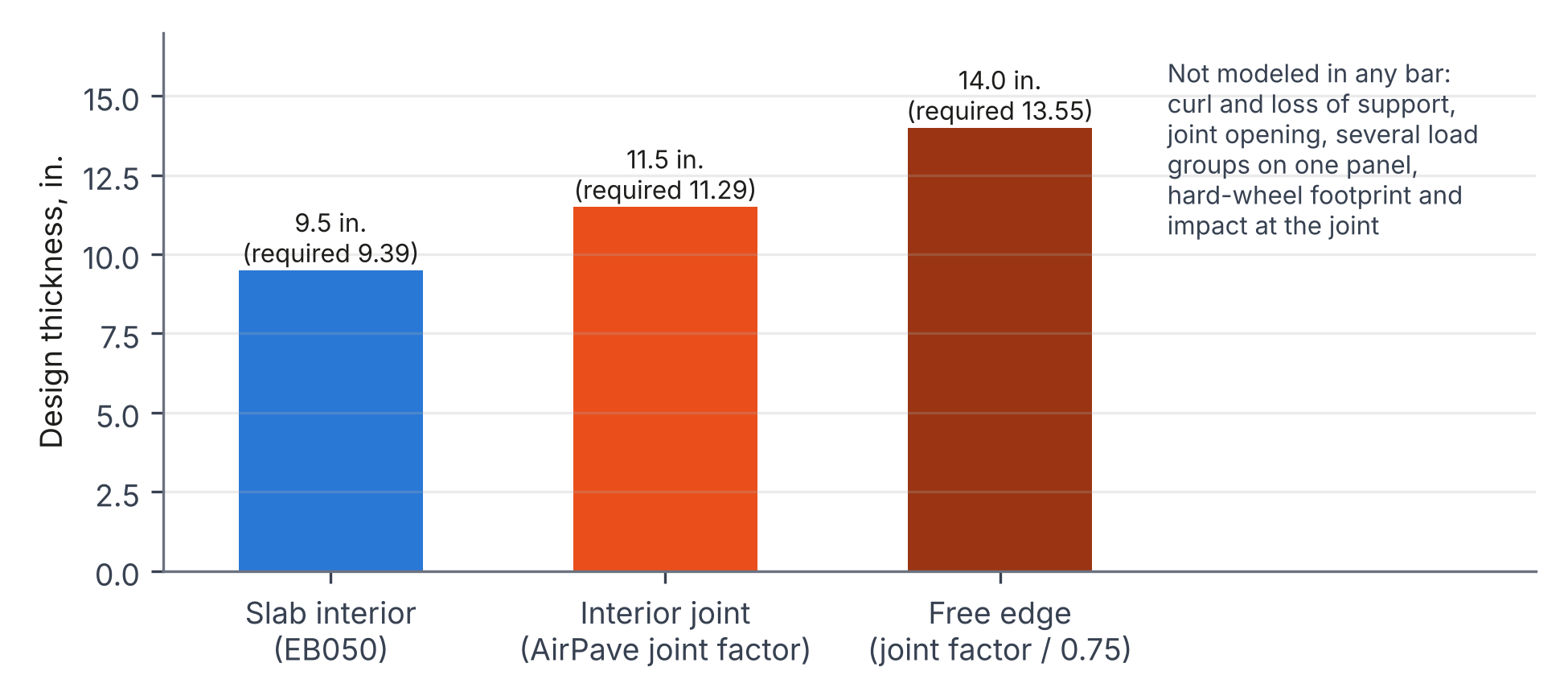
And that is only load position, treated as a multiplier. It does not include:
- Curl and loss of support. ACI 360R-10 reports curling stresses of 200 to 450 psi, the same order as the load stresses a design allows. They cannot simply be added to a load stress. A curled slab lifts off its support at its joints and corners; a load there pushes it back down, so the contact area, the stress distribution, and even the face in tension change with the size and position of the load. A wheel at a curled joint is carried partly as a cantilever, with tension at the top. This is a contact problem in which curl and load have to be solved together, on the support that is actually there, and the method does neither.
- Load transfer as a variable. The airport method assumes it; AirPave fixes it at a 25% stress reduction. Dowels, aggregate interlock, and joint opening are not inputs.
- Several load groups on one panel. PDILB combines the wheels of one gear, a single load group, and positions that group for the maximum moment. It does not combine separate load groups acting on the same panel. For aircraft that is reasonable: the main gears are far apart, and their interaction on one slab is small. Industrial floors concentrate loads much more closely, and the method was not built to look for that interaction. This is the same mismatch in another form: an application drove the software's needs, and the software is then used, unchanged, in an application with different load concentrations.
- Hard-wheel contact. The method models every wheel as a pneumatic tire, with an elliptical imprint whose area is the wheel load divided by the inflation pressure. Small solid and polyurethane wheels do not bear that way. Their contact is a narrow strip across the wheel width, closer to a short line load than to a tire imprint, so an imprint computed from an assumed pressure represents a tire, not the wheel being designed for. The wheel's impact on a joint edge is not a flexural stress at all.
- Support. A higher k lowers the computed interior stress, but a stiff base also restrains the slab and increases curl, which the method does not see.
A High but Unknown Factor of Safety
None of this means floors designed with the airport method have performed badly. Many have performed well, and the reason is worth stating plainly. An interior stress, a safety factor of about 2, and EB050's thick-pavement habits produce generous slabs, and the factor of safety has absorbed effects the method never computed.
The arithmetic for the load alone shows how much of that factor of safety is spoken for. A slab sized for a safety factor of 2.0 at the interior has a safety factor of about 2.0 / 1.77 = 1.13 at a free edge using AirPave's free-edge factor, and about 2.0 / 1.33 = 1.50 at an interior joint with AirPave's joint factor.
Curl cannot be stacked on top of those numbers. Adding a curling stress to a load stress, as is sometimes done, treats the slab as if it stayed in full contact with its support, and a curled slab does not: the load changes the support, and the support changes the stress. Depending on the curl, the load, and where it sits, the combined stress at a joint can be well above or below the simple sum, and the critical tension can move to the top of the slab. The only way to know is to model curl and load together.
The capacity side of the ratio is just as incomplete. The modulus of rupture is measured on a small, simply supported beam. A slab-on-ground differs from that beam in geometry, support, and stress distribution, it can redistribute load, and it carries more than the beam strength suggests. Elastic stresses computed with curl, loss of support, and the loads on a panel, compared against the beam modulus of rupture, would predict cracking in many floors that have performed well. For that reason, SLABS converts beam strength to slab capacity with a thickness-dependent geometry factor, with a separate factor for fibers (Covarrubias et al., 2026). Both sides of the ratio, the demand with curl and load solved together and the slab's actual capacity, have to be right before the equations can begin to explain the performance record of slabs-on-ground. EB050 computes the demand at the interior only and compares it with a beam, and its safety factor has been covering the difference in both directions.
The actual factor of safety of an airport-method floor is therefore high in the interior and unknown at its joints, and it stays unknown until the conditions the method leaves out are accounted for.
That is the honest description of the standard of practice: the method has served the industrial space for decades with a high factor of safety whose value the author has not found computed. It does not support thinner slabs, and it does not support the claim that a floor designed this way was designed for its joints.
Stepping Stones
Both PCA bulletins were written to be improved, and the 1955 edition said so. Its appendix explains that the dense-liquid subgrade was chosen because the elastic-solid alternative could not yet be applied in practice, then adds: "work on the elastic solid subgrade assumption is continuing and it is believed a practical solution soon will be found. Until the application of the elastic solid theory is developed, the method herein presented may be used with assurance that it will give safe results." The method was offered as safe for its time and its conditions, pending something better.
The revisions followed, three editions in 23 years: 1950, 1955, and 1973. Between 1955 and 1973, EB050 moved from hand-counted influence charts to the PDILB program, from the 28-day modulus of rupture increased 10 to 14% to a 90-day design modulus of rupture with an allowance for strength variability, from a table of stress repetitions per 100 operations to load repetition factors and a fatigue analysis with Miner's hypothesis, and from a safety factor of 1.25 to 1.5 for the central portion of runways to 1.4 to 1.7. EB075 went from Packard's 1976 charts and 1978 and 1983 editions that handled joints by judgment and thickened free edges, to joint factors in 2001 and free-edge charts in 2008. Each revision added what the previous one lacked, in the way engineering guides are supposed to work.
Then, for floors, the consensus guidance stopped (Figure 5). Finite element programs that model joints and load transfer, such as ILLI-SLAB (Tabatabaie and Barenberg, 1978), have existed for nearly 50 years. Highway design moved to mechanistic-empirical methods with NCHRP Project 1-37A (2004). The FAA moved rigid airfield design to edge stresses computed by three-dimensional finite elements in FAARFIELD (2009), and ICAO replaced the PCA program with layered elastic analysis in its ACR-PCR method (2024). The method PCA built for airports has been retired by the airport community, while the industrial floor community still borrows it.
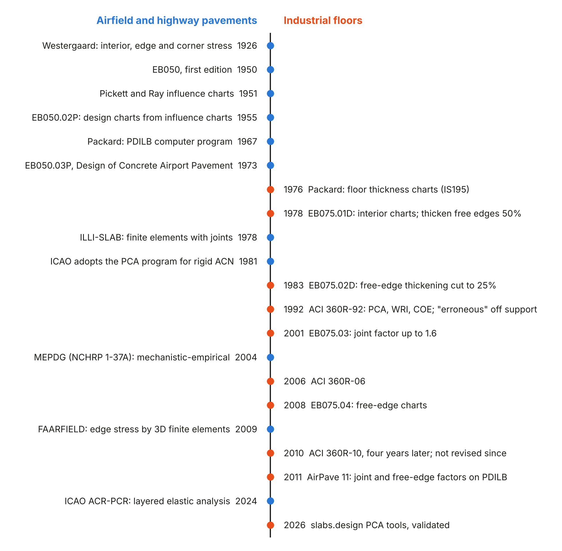
ACI 360R-10, published in 2010, cites the 2001 edition of the floor method and works its examples without the joint factor. The committee's first guide, ACI 360R-92, had already said it. It presented the same three methods, PCA, WRI, and COE, and stated that because all three assume the slab is always fully supported, "they give erroneous results for slab thickness where the slab is not in contact with the subgrade." It described finite elements as offering "good potential for complex problems" with limited use in typical design, and added that "microcomputers may enhance its usage... in the future." The guide was revised in 2006 and again in 2010, four years later, with the same three methods and the same sentence, and it has not been revised since. Computational power, finite element analysis, and mechanistic-empirical modeling advanced quickly over the same period. The consensus guidance did not follow. Innovation in floor design did not stop; it moved outside the committees, into proprietary flooring systems, admixtures, dowel and fiber design software, and mechanistic-empirical tools such as SLABS.
The two documents follow the same pattern. PCA revised its airport method five years after first publishing it, and ACI revised its floor guide four years after the 2006 edition, while the work was fresh and its authors could see what it lacked. Once a method is established, the same recognition comes more slowly. Its flaws are just as visible, but by then it is embedded in specifications, software, practice, and the standard of care, and a long record of floors that performed well is easily read as validation of the method rather than of the factor of safety that carried it.
Conclusions
The airport method is a sound statement of interior-load theory, and the rebuilt version reproduces Packard's printed computer output to the fourth decimal where the source allows it. Its value to industrial engineers came from flexible inputs, and that flexibility is real. A design basis, though, is the combination of a model, a performance criterion, and the distress it was calibrated against. EB050 brings an interior load on an infinite, fully supported slab; safety factors and a fatigue curve calibrated to airfields with load transfer at every joint; and no criterion for the joint deflection that industrial guidance limits. Applied without those differences in mind, it does not add up for floors carrying small, hard wheels across sawcut joints.
The factor of safety of an airport-method floor is high in the interior and unknown at the joints. Closing that gap takes the step both PCA bulletins were pointing toward: a mechanistic-empirical model of the slab as it is, with joints, load transfer, curl and load solved together rather than added, loss of support, and the actual loads on a panel, compared with the capacity of the slab rather than the beam, and calibrated to the distress floors actually show. The Slab Designer's work is to bring theory, guidance, and design for slabs-on-ground up to that standard. The rebuilt PCA tools are part of it: they make the published methods reproducible, show their bounds, and make plain where they stop.
References
1.Packard, R. G. Design of Concrete Airport Pavement. EB050.03P. Portland Cement Association, Skokie, Ill., 1973. https://zemubarek.wordpress.com/wp-content/uploads/2014/04/design-of-concrete-airport-pavement.pdf
2.Portland Cement Association. Design of Concrete Airport Pavement. EB050.02P. Portland Cement Association, 1955.
3.Packard, R. G. Computer Program for Airport Pavement Design. SR031P. Portland Cement Association, Skokie, Ill., 1967.
4.Westergaard, H. M. Stresses in Concrete Pavements Computed by Theoretical Analysis. Public Roads, Vol. 7, No. 2, 1926, pp. 25 to 35.
5.Pickett, G., M. E. Raville, W. C. Janes, and F. J. McCormick. Deflections, Moments, and Reactive Pressures for Concrete Pavements. Bulletin No. 65. Kansas State College, Manhattan, 1951.
6.Pickett, G., and G. K. Ray. Influence Charts for Concrete Pavements. Transactions of the American Society of Civil Engineers, Vol. 116, 1951, pp. 49 to 73.
7.American Concrete Pavement Association. AirPave Airport Pavement Design Program, User's Manual. MC006P, rev. 10-2011. Rosemont, Ill., 2011.
8.Packard, R. G. Slab Thickness Design for Industrial Concrete Floors on Grade. IS195.01D. Portland Cement Association, Skokie, Ill., 1976.
9.Portland Cement Association. Concrete Floors on Ground. EB075, 3rd ed. Skokie, Ill., 2001.
10.Farny, J. A., and S. M. Tarr. Concrete Floors on Ground. EB075, 4th ed. Portland Cement Association, Skokie, Ill., 2008.
11.ACI Committee 360. Guide to Design of Slabs-on-Ground. ACI 360R-10. American Concrete Institute, Farmington Hills, Mich., 2010.
12.Tabatabaie, A. M., and E. J. Barenberg. Finite-Element Analysis of Jointed or Cracked Concrete Pavements. Transportation Research Record 671, 1978, pp. 11 to 19.
13.ARA, Inc. Guide for Mechanistic-Empirical Design of New and Rehabilitated Pavement Structures. NCHRP Project 1-37A. Transportation Research Board, Washington, D.C., 2004.
14.Federal Aviation Administration. Airport Pavement Design and Evaluation. Advisory Circular 150/5320-6E, with FAARFIELD. Washington, D.C., 2009.
15.International Civil Aviation Organization. ACR-PCR Concepts. Workshop on Aerodrome Pavement, 2024. https://www.icao.int/sites/default/files/APAC/Meetings/2024/2024%20Workshop%20on%20Aerodrome%20Pavement/5-Presentations/WK6-ACR-PCR-Concepts_MUNIZ.pdf
16.Parkes, N., and R. Rodden. Full Support, Interior Loads, and the Missing Joint Factor: The Thickness Methods of ACI 360R-10 and Their PCA Lineage. Technical Paper TSD-05TP. The Slab Designer, LLC, 2026. https://slabs.design/knowledge/thickness-methods/paper
17.The Slab Designer, LLC. PCA Airport Thickness Design. https://slabs.design/pca-airport. Accessed October 2026.
18.The Slab Designer, LLC. PCA Slab Thickness Design. https://slabs.design/pca. Accessed October 2026.
19.Covarrubias, J. P., R. Rodden, L. Khazanovich, J. Roesler, and N. Parkes. Mechanistic-Empirical Design of Concrete Slabs-on-Ground. Concrete International, American Concrete Institute, July 2026.
20.ACI Committee 360. Design of Slabs on Grade. ACI 360R-92 (Reapproved 1997). American Concrete Institute, Detroit, Mich., 1992.
21.ACI Committee 360. Design of Slabs-on-Ground. ACI 360R-06. American Concrete Institute, Farmington Hills, Mich., 2006.
22.Rodden, R. Two Promises in the Floor Design Guide That Curling Breaks. Article TSD-07A. The Slab Designer, LLC, 2026.
22.Spears, R. E. Concrete Floors on Ground. EB075.01D. Portland Cement Association, Skokie, Ill., 1978.
23.Spears, R. E., and W. C. Panarese. Concrete Floors on Ground. EB075.02D, 2nd ed. Portland Cement Association, Skokie, Ill., 1983.
Related in This Series
- Article on this topic: Your Warehouse Floor Is Not a Runway
Why an airport design method ended up sizing forklift floors, and why matching inputs is not the same as matching the problem.
- Raised but Not Resolved: An Audit of ACI 360R-10
Audits eight design decisions in ACI 360R-10 for whether each issue raised is carried through to a design method.
- The Thickness Methods of ACI 360R-10 and Their PCA Lineage
Traces how PCA added a joint factor in 2001 and 2008 that ACI 360R-10's thickness procedure still omits.
- From Westergaard and Meyerhof to Mechanistic-Empirical Design
Summarizes the 2026 Concrete International and Concrete articles that set out why the Westergaard and Meyerhof methods fall short for modern floors and how the SLABS framework addresses it.
- Light Reinforcement Through Sawcut Joints: Tolerances and the JRCP Record
Thickness tolerances push as-built steel ratios past 0.1%, and the highway record of JRCP shows where that detail leads.
Revision history
- November 4, 2026: Revised the airfield joint discussion; adopted slab interior, interior joint, and free edge terms; added wheel footprint and multiple load groups; added PCA's 1973 jointing plan; added metric units to k-values.
- November 3, 2026: First published on slabs.design/knowledge.
To cite this paper, use the citation printed in the PDF. It includes the revision date, so readers can match your citation to the text you read.