Technical Paper|TSD-01TP
The Evolution of Concrete Pavement Design in the United States and Its Lessons for Slabs-on-Ground
Robert Rodden (The Slab Designer, LLC); Juan Pablo Covarrubias (TCPavements-FORTA)
The Slab Designer, LLC | Published October 20, 2026 | Revised November 8, 2026
Abstract
Concrete pavement design in the United States developed over more than a century through a sequence of practical problems and the solutions engineers adopted to address them. Pavements were first built for rut resistance, with joint spacing set by mixer capacity and no structural design. As traffic speed, volume, and loads grew, designers responded in turn to shrinkage cracking, crack deterioration, faulting, blowups, pumping, and joint roughness, and each response introduced new elements: reinforcement, contraction and expansion joints, dowels, subbases, sawed joints, and finally mechanistic-empirical design. The record is distributed across test-road reports, agency studies, design guides, and trade literature, and it is rarely presented as a single sequence. This paper assembles that sequence around the design challenges that drove it, traces how three pavement types (jointed plain, jointed reinforced, and continuously reinforced) branched from it, and summarizes why highway agencies converged on the first and third and largely abandoned the second. It then sets the parallel development of slabs-on-ground alongside the pavement record. Floor design borrowed its theory from pavements, including the Westergaard solutions, the modulus of subgrade reaction, the PCA thickness charts, and aggregate interlock data, but in recent decades floors have led in construction innovation while their design methods have changed less. The comparison identifies lessons from the pavement record that apply directly to floors, particularly on restraint, light reinforcement, joint spacing, load transfer, and uniformity of support. The paper also traces the development of optimized-geometry slabs and of the OptiPave and OptiSlab software, which carried finite element analysis and fatigue models from pavements to floors.
Keywords: concrete pavement history, jointed plain concrete pavement, jointed reinforced concrete pavement, continuously reinforced concrete pavement, slab-on-ground, design evolution
Introduction
This paper grew out of a presentation one of the authors (Rodden) first assembled at the American Concrete Pavement Association in 2014, prompted by ACPA's resident historian, Larry Scofield, and has since given more than a dozen times: an attempt to document why concrete pavement design got where it is. The short answer is trial and error, a great deal of it, from corduroy log roads to tooled joints, thickened centerlines, thickened edges, and expansion joints made necessary by long panels.
A designer who picks up a modern concrete pavement or floor specification inherits decisions made over a hundred years: why joints are spaced as they are, why dowels are smooth, why most highway pavements carry either no distributed steel or a great deal of it, and why thickness charts begin from a load in the middle of a slab on a uniform foundation. Most of those decisions were made in response to a specific problem, and many were revised more than once as the problem changed. Few current documents explain them in sequence, so the reasoning behind a detail is easily lost even as the detail survives.
This paper has two aims. The first is to assemble the history of concrete highway pavement design in the United States as a sequence of design challenges and solutions, with sources, so that the logic of current practice is visible. The second is to place the development of slabs-on-ground alongside it. Floors and pavements share most of their mechanics, and floor design has drawn on pavement research from its beginning. Comparing the two shows where floor practice has gone further than pavements, where it has lagged, and where it has adopted pavement practices that pavement engineers themselves set aside.
The paper is limited to cast-in-place concrete pavements for streets, roads, and highways in new construction. Roller-compacted, pervious, and precast pavements, airfield pavements, and overlays are mentioned only where they bear on the main sequence.
The Early Pavements: Rut Resistance, Not Structure
The First Concrete Pavement
The first concrete pavement in the United States was built in Bellefontaine, Ohio, around the courthouse square, in 1891 (some sources give 1892) (1, 2). George Bartholomew, who produced cement locally, proposed it to address a problem every town of the period shared: horseshoes and steel-rimmed wagon wheels rutted unpaved and macadam streets, which turned to mud in wet weather. The pavement was placed in narrow strips in two lifts, with hard aggregate near the surface to resist wear, and was scored into a grid so that horses would not slip. Bartholomew posted a bond and a five-year performance warranty as a condition of approval. Portions of the pavement remain in service (2).
The design challenge was surface durability, and the solution was a hard, rut-resistant surface. Nothing about the pavement was structurally designed. Its thickness was chosen by judgment, and its joints were wherever one batch ended and the next began.
Joints Set by the Mixer
Concrete pavements spread quickly in the first two decades of the 20th century. The first mile of rural concrete pavement was built in Wayne County, Michigan, in 1909 on Woodward Avenue (1, 3). A concrete overlay on asphalt was placed as early as 1901 and a concrete overlay on concrete by 1913, and in 1913 a 24-mile concrete highway, 5 in. (130 mm) thick and 9 ft (2.7 m) wide, was built near Pine Bluff, Arkansas (1). By 1914 about 2,348 miles of concrete roadway existed (1). The Federal-Aid Road Act of 1916 began federal participation in highway construction (1).
Typical pavements of the period were about 6 in. (150 mm) thick. Slabs were placed in squares of roughly 6 to 8 ft (1.8 to 2.4 m), a dimension set by the capacity of the mixer rather than by any analysis of cracking, and they had no dowels, reinforcement, or sawed contraction joints (4). The short slabs, while not designed for the purpose, limited the restraint that later became the central problem of jointing.
Longer and Wider Slabs: the Problem of Restraint
Minimizing Joints
As vehicle speeds rose, drivers noticed the roughness of frequent hand-formed construction joints, and contractors sought to minimize joints to increase production and reduce cost. Better equipment allowed longer placements, and the demand for two-lane roads for safety produced wider slabs. Both changes exposed a property of concrete that short slabs had concealed: it shrinks.
Concrete shortens as it cools from the temperature at set, as cement hydration consumes water (chemical and autogenous shrinkage), and as it dries. A slab free to move would simply become shorter. A slab on the ground is restrained by friction with the material below it, and in a long slab the restraint accumulates until the tensile stress exceeds the strength of the young concrete and the slab cracks. Longer slabs produced transverse cracks; wider slabs produced erratic longitudinal cracks.
Early Responses to Cracking
The first responses accepted the cracks and tried to manage them. Wide pavements were built with thickened centers to resist longitudinal cracking, and transverse cracks were allowed to form at their natural spacing, typically 15 to 20 ft (4.6 to 6.1 m) in slabs with 40 to 80 ft (12 to 24 m) between joints (4). Until about 1922, most wide pavements were built without a longitudinal joint and with a thickened center section (4). The erratic longitudinal crack that developed in most 16 to 18 ft (4.9 to 5.5 m) wide pavements was eventually controlled by forming a longitudinal joint and tying it with deformed bars, a practice that became general when two-lane roads were divided into lanes of about 10 to 12 ft (1, 4).
Holding Cracks Tight: The Origin of Jointed Reinforced Pavement
Uncontrolled transverse cracks opened, spalled, and lost the ability to transfer load. Designers responded by adding distributed steel to hold the cracks tightly closed. This produced the jointed reinforced concrete pavement (JRCP), with joints at long spacings, commonly 40 to 100 ft (12 to 30 m), and distributed steel of roughly 0.1 to 0.25% of the cross section to keep the intermediate cracks tight (4, 5). The amount of steel was set by the subgrade drag theory, which balances the friction acting on half a panel against the allowable tension in the steel (5, 6). Reinforced pavements appear in the record by 1913 or earlier (4), and by the 1930s most concrete highway pavement in the United States was JRCP (1).
The subgrade drag approach is worth noting because it persists in slab-on-ground practice. It treats the steel as holding a crack closed against friction alone and gives no information about curling stresses or about the redistribution of movement among joints. A version of it appeared in ACI 360R-92 and was later removed because it was producing problematic designs (7).
Making the Cracks Straight: Contraction Joints
Even tight cracks were difficult to maintain, and their irregular paths made sealing impractical. The next step was to decide where the cracks would form by creating straight transverse contraction joints at closer spacing, initially by hand-forming grooves in the plastic concrete and later by inserting strips. Hand-formed joints were rough under traffic, which kept the pressure on designers to minimize their number.
Load Transfer: Dowels
Construction joints and the wider cracks faulted and chipped under traffic as one side of the joint deflected more than the other. Smooth steel dowels across the joint, free to slide in one side so that the joint could still open and close, were introduced to carry load from one slab to the next. The first doweled joints are generally dated to about 1917 (4), and doweled jointed plain pavement (JPCP) and doweled JRCP developed from that point.
Blowups and Expansion Joints
Long panels and wide joints let incompressible material into the joints, and in hot weather the restrained slabs had no room to expand. The result was blowups. Designers responded by adding expansion joints, which created their own problems. In the 1940s the U.S. Bureau of Public Roads studied expansion joints and found that they progressively closed over the years, which caused greater opening at nearby contraction joints, loss of aggregate interlock, and sealant failure. The Bureau concluded that expansion joints were unnecessary unless contraction joints were spaced at more than about 60 ft (18 m), the aggregates were expansive, or the pavement was built near freezing temperatures (1). The finding is an early, clear statement of a principle that recurs throughout this history: restraining or freeing one joint changes the movement at its neighbors.
Continuously Reinforced Pavement
The opposite approach to cracking was also tried early. Instead of holding a few widely spaced cracks with a little steel, continuously reinforced concrete pavement (CRCP) eliminates transverse contraction joints and uses enough longitudinal steel, typically about 0.6% and up to about 0.7% in severe climates, to produce many fine cracks at close spacing, about 2 to 6 ft (0.61 to 1.8 m) apart (8, 9). Read against the JRCP story, CRCP is a telling development: when a little distributed steel did not keep cracks tight, the response was not to refine the small amount but to add a great deal more and remove the joints. The first CRCP in the United States was built in 1921 on Columbia Pike near Washington, D.C., for experimental purposes (8); other sources date the first CRCP to 1923 (1). States studied CRCP through the 1940s and 1950s, and its extensive use began in the early 1960s during construction of the Interstate System (8).
The Beginning of Structural Design
Test Roads
Structural design in the modern sense began in the 1920s with full-scale test roads. The Pittsburg, California, test of 1921 and 1922 compared plain and reinforced pavement sections under traffic and found no clear benefit from the reinforcement (1). The Bates test road in Illinois, constructed in 1920 with additional thickened-edge sections in 1922, loaded more than 60 sections, 32 of them concrete, with trucks on solid rubber tires and produced the first thickness design procedures (10). Thickened edges, adopted because the tests showed edge stresses governed, became common and were dropped in the 1940s as lanes widened and traffic moved away from the pavement edge (1).
Westergaard
In 1926 H. M. Westergaard published closed-form solutions for the stress and deflection of a concrete slab on an elastic foundation under a load at the interior, edge, and corner (11). To make the problem tractable he idealized the foundation as a bed of independent springs characterized by a single modulus of subgrade reaction, k, and assumed the slab to be in full contact with it. The solutions showed that edge and corner loads produce much higher stresses than interior loads and gave engineers the first rational basis for thickness. Westergaard's work, and the k-value it introduced, became the foundation of the Portland Cement Association's thickness design for pavements in the 1930s and, through it, of later floor design (12).
Subbases and Pumping
Heavier and more frequent truck traffic before and during World War II revealed pumping: the ejection of water and fine soil from beneath slab edges and joints under repeated loads, leaving voids that led to faulting and cracking. The response was the granular subbase, introduced in the 1930s, followed in the 1940s by soil-cement subgrades and the first cement-treated bases, the latter first built in California (1).
World War II
During the war the Bureau of Public Roads encouraged steel-free designs to conserve steel. Undoweled jointed plain pavement with expansion joints at 105 to 120 ft (32 to 37 m) became the norm. These pavements were relatively free of cracking, spalling, and blowups, but their contraction joints opened wide, aggregate interlock was lost, and faulting was serious (1). After the war, practice divided between undoweled JPCP with short joint spacing and no expansion joints and long-jointed JRCP with contraction and expansion joints at 50 to 100 ft (1, 4).
Durability
Deicing salts, widely used after the war, caused surface scaling, and entrained air was introduced to resist freeze-thaw damage in the 1940s (1). Durability has remained a materials question since, and it is outside the scope of this paper.
Construction Innovation and the AASHO Road Test
Two construction developments changed the economics of jointing. Contractors began sawing contraction joints in hardened concrete in the 1940s, producing straight, smooth joints, and the first slipform paver was introduced in 1949 (1). Together, slipform paving and sawed joints made short-jointed JPCP the most economical concrete pavement to build (1, 4). By the 1950s lean concrete bases were in use for erosion resistance, and prestressed pavements were being tried (1).
The Federal-Aid Highway Act of 1956 created the Interstate System, and the AASHO Road Test of 1958 to 1960 near Ottawa, Illinois, applied controlled truck traffic to rigid and flexible test sections, with the intent of loading them to failure. Most of the concrete sections still had good serviceability when testing ended, far from failure on their performance curves. Two years of traffic was too short to characterize concrete pavement performance, although it did a reasonable job of characterizing the asphalt sections. The resulting empirical relationships among thickness, traffic, and serviceability became the AASHO Interim Guide of 1961 and 1962 and, through the AASHTO guides of 1972, 1986, and 1993, the basis of most agency design for four decades (1, 13). In the 1960s many joints were skewed to reduce the dynamic effect of axles crossing them, sometimes in place of dowels; the first concrete shoulder was built in 1964; and in 1976 Congress funded restoration, rehabilitation, and resurfacing, recognizing the importance of maintenance (1). By the 1980s, joints in new highway pavements were almost always doweled (1).
Convergence on Two Pavement Types
Performance Evidence
From the 1970s onward, agency and FHWA studies examined the performance of in-service concrete pavements on a national scale. The FHWA Performance of Jointed Concrete Pavements program (14) and later studies of in-service sections across North America (15) quantified the effects of joint spacing, load transfer, slab thickness, reinforcement, and drainage. For JRCP, deteriorated transverse cracking was associated with low steel percentages, cold climates, and long panels, and the program recommended a minimum of 0.1% distributed steel, with more for harsher climates and longer slabs (14, 23). That figure was a floor for JRCP, not a ceiling. The basic problem was that the light steel was not enough to keep the intermediate cracks tight, all things considered. The cracks opened far enough that aggregate interlock was lost, and the distributed steel was too little to carry load across the crack on its own, so the cracks faulted and spalled (16). PCA's floor manual also attributes some of this poor performance to steel yielding caused by malfunctioning doweled joints (23).
The Outcome
By the end of the 20th century, state agencies had largely settled on two pavement types: JPCP with short joint spacing, typically doweled on routes with heavy truck traffic, and CRCP where long life justified its cost (5, 9, 17). JRCP fell out of favor because of inferior performance compared with JPCP and CRCP, and by 2001 only a handful of agencies still used it (5). The national mechanistic-empirical procedure developed under NCHRP Project 1-37A and adopted by AASHTO covers JPCP and CRCP; JRCP "were not directly considered in the MEPDG development and cannot be designed using this procedure" (18). The Texas Department of Transportation, among the last agencies to retain the type, states that JRCP "is no longer endorsed by the department" (19). Table 1 summarizes the three types.
Table 1. Comparison of Jointed Plain, Jointed Reinforced, and Continuously Reinforced Concrete Pavement
| Feature | JPCP | JRCP | CRCP |
|---|---|---|---|
| Transverse joint spacing | About 15 to 20 ft | About 40 to 100 ft | None |
| Transverse crack spacing | Cracks at joints | About 15 to 20 ft | About 2 to 6 ft |
| How shrinkage is accommodated | Jointing | Joints plus held cracks | Many fine cracks |
| Distributed steel | None | About 0.1 to 0.25% | About 0.6 to 0.7% |
| Expansion joints | Not needed | Sometimes used | At structures |
| Longitudinal joints | Tied, about 12 ft | Tied, about 12 ft | Tied, about 12 ft |
| Designed by AASHTO 1993 guide | Yes | Yes | Yes |
| Designed by AASHTOWare Pavement ME | Yes | No | Yes |
| Current highway status | Most common | Largely discontinued | In use for long life |
The convergence reflects a principle that the century of trial and error made clear. A jointed pavement performs best when restraint is minimized, with joints close enough that each opens a small, predictable amount and load transfer provided where traffic requires it. A continuous pavement performs best when restraint is maximized, with enough steel to force many fine cracks and hold all of them tight. JRCP sits between these. It has too much restraint at its intermediate cracks to let them work as joints and too little steel to control them as CRCP does, so its performance depends on the steel and the joints functioning exactly as intended over the life of the pavement.
Design Methods Since the Road Test
The decades since the Road Test have refined rather than replaced these systems: production improvements such as stringless paving and dowel bar inserters, optimized aggregate gradation, widened slabs, attention to curing, and dowel materials and geometry (1). Thickness design moved from the empirical AASHTO guides toward mechanistic-empirical methods, including ACPA's StreetPave in 2005 and 2012 and the AASHTO mechanistic-empirical procedure, released as DARWin-ME in 2010 and AASHTOWare Pavement ME Design in 2013 (1, 18). These methods compute stresses from loads and from temperature and moisture gradients, include curling and loss of support, relate load transfer to joint opening, and calibrate damage to observed cracking and faulting. Long-life concrete pavement, designed for 40 years of service or more, was the subject of an FHWA international conference in 2006 (20).
Optimized-Geometry Slabs and the Development of OptiPave
The convergence on short-jointed plain pavement left one design question open: how short the panels should be. Standard JPCP uses panels about 12 ft (3.7 m) wide and 15 to 20 ft (4.6 to 6.1 m) long (Table 1). In 2005, a concrete pavement concept was introduced in Chile in which the panel dimensions are chosen from the geometry of the truck axles, so that only one wheel or one set of wheels loads a panel at a time (28, 29). The smaller panels reduce both curling stresses and the interaction between loads. According to the developers, this allows a lower thickness for the same design life, or a longer life for the same thickness, and makes dowels unnecessary at the sawed joints because the joint opening is smaller (28). Read against the pavement record in this paper, the concept takes the jointed end of the convergence further: it minimizes restraint through geometry instead of through steel.
The concept was developed as a design method, not as a joint detail. The first designs, in 2007, used ISLAB2000 finite element analysis followed by a fatigue check. Accelerated testing at the University of Illinois in 2008 provided calibration data, and spreadsheets built on databases of ISLAB2000 stresses followed in 2008 and 2009. The first software release, OptiPave 1, appeared in 2010 and was calibrated against test results. In 2013, OptiPave 2.0 replaced the stress databases with neural networks trained on finite element results, and the Java version of 2014 was calibrated with further accelerated pavement tests. Cracking is predicted with the fatigue and performance models of the interim mechanistic-empirical guide (18), calibrated against full-scale test sections (29). The software was incorporated into the concrete overlay design guide of the National Concrete Pavement Technology Center in 2015, the TCP method was recognized in ACI 330.2R-17 in 2017 (30), and OptiPave 2.5 added improved faulting models and new calibrations in 2018 (31). Table 2 summarizes the sequence. The monitoring of public projects built with the concept in Chile after more than a decade of use is reported in (28).
Table 2. Development of OptiPave, 2005 to 2018 (Developer's Records, 31)
| Year | Milestone |
|---|---|
| 2005 | Optimized-geometry slab concept for pavements (TCP) |
| 2007 | First designs with ISLAB2000 and a subsequent fatigue analysis |
| 2008 | Accelerated testing at the University of Illinois; calculation spreadsheet based on ISLAB2000 data |
| 2010 | OptiPave 1 released, calibrated with test results |
| 2013 | OptiPave 2.0: neural networks for stress calculation |
| 2014 | Java version, calibrated with accelerated pavement tests |
| 2015 | Incorporated into the National Concrete Pavement Technology Center concrete overlay design guide |
| 2017 | TCP method recognized in ACI 330.2R-17 |
| 2018 | OptiPave 2.5: improved faulting models, new calibrations |
The Parallel Development of Slabs-on-ground
Borrowed Theory
Floor design has drawn on pavement research from the start. PCA describes its floor thickness method as based on "extensive data from many years of laboratory and field research and testing from highway pavement engineering," notes "many similarities between an unreinforced road pavement and a plain concrete floor slab," and states that "stress, deflection, and fatigue analytical approaches of pavement design are applicable to slabs on ground" (12). The PCA floor charts were first presented by Packard in 1976, based on Westergaard's solutions and influence charts developed for pavements (12, 21). ACI 360R-10 traces all three of the thickness methods it presents, PCA, WRI, and COE, to Westergaard, and its aggregate interlock data come from PCA's 1967 pavement joint tests (7, 22). PCA's joint factor for loads at joints without load transfer, introduced in the 2001 edition of Concrete Floors on Ground, was based on finite element analysis with ILLI-SLAB, a pavement program (12, 23).
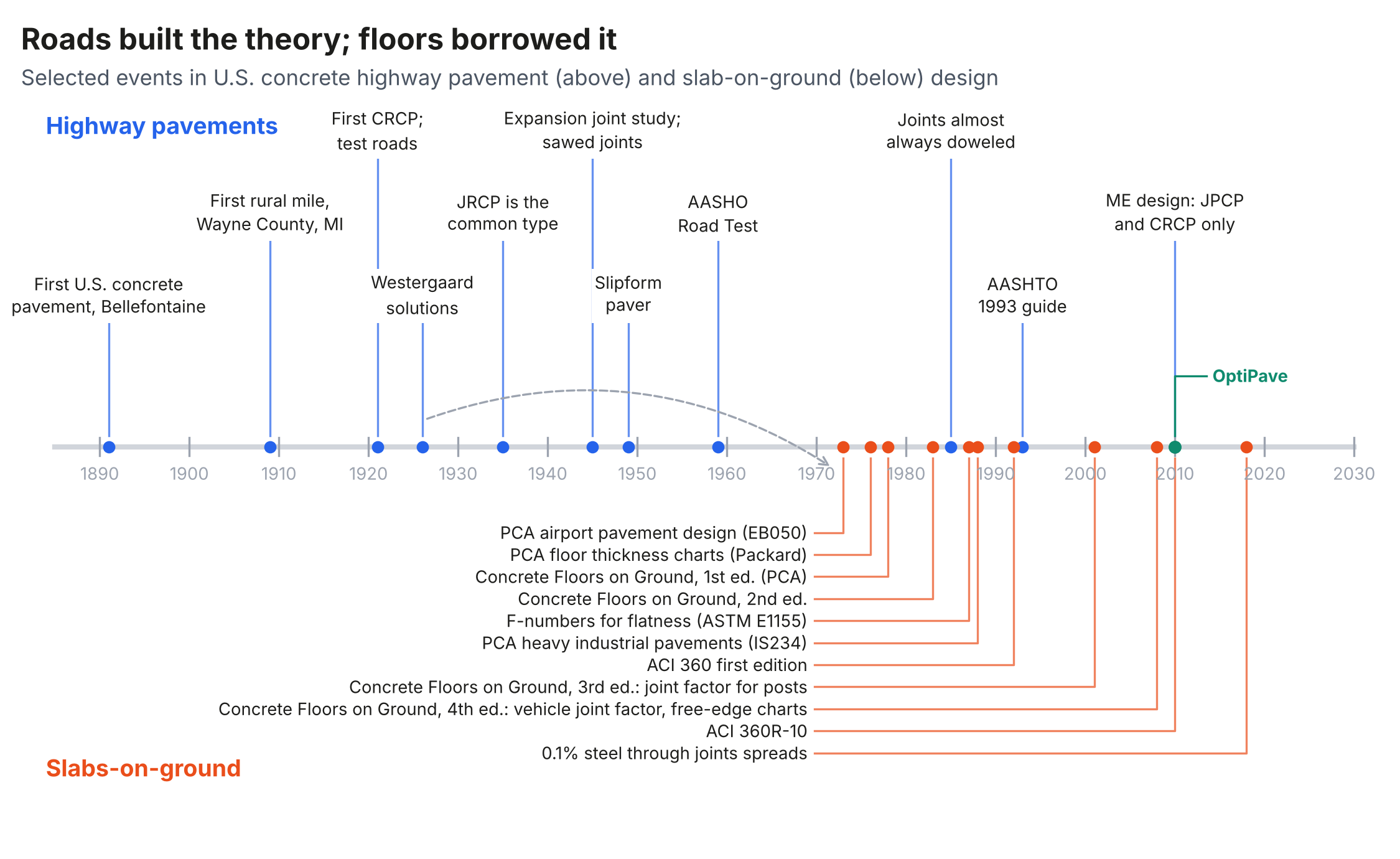
Construction Leadership
In construction, floors have moved faster than pavements in several respects. Laser-guided screeds, the F-number system for specifying and measuring floor flatness and levelness (ASTM E1155, first published in 1987), early-entry dry-cut saws that cut joints within hours of finishing, power pan floats, plate dowels that accommodate movement in two directions, steel and macrosynthetic fibers, shrinkage-compensating concrete, and post-tensioned slabs all developed in or were adapted extensively to the floor market (7, 12). Floors are built under controlled conditions to tighter tolerances than most pavements, and owners can see and measure the results.
Design Lag
Floor design methods have changed less. ACI Committee 360 published ACI 360R-92 (57 pages, from a committee of 11), ACI 360R-06 (74 pages, from a committee of 29, of whom about 10% had served on the 1992 committee), and ACI 360R-10 (72 pages, with 86% of the 2006 membership) (7, 26). The 2006 edition was introduced to structural engineers as bringing "Slabs on Ground Design into the 21st Century" (27); its thickness methods were the Westergaard-based procedures of the 1920s through the 1970s. Sixteen years after the 2010 edition, the committee has 33 members, about a third of whom served in 2010. The 2010 guide presents three thickness methods that rest on Westergaard's assumptions of full and uniform support and states that, for that reason, they "give erroneous results for slab thickness where the slab is not in contact with the subgrade" (7). The PCA method, in its worked examples in ACI 360R-10, is used without the joint factor that PCA had already adopted (7, 12, 23). Curling, which ACI 360R-10 places at 200 to 450 psi (1.4 to 3.1 MPa) of stress, is discussed at length but not included in the thickness calculation (7). Mechanistic-empirical design of the kind adopted for highways in 2008 to 2013 has only recently begun to appear for floors (24, 31).
The asymmetry has a plausible explanation. Pavement research is funded by public agencies responsible for large networks, with test roads, national performance databases, and federal programs. Floor research is funded largely by private owners, contractors, and suppliers, with far less shared performance data. PCA's floor manual leans on pavement research throughout. It justifies the k-value because "substantial pavement research has shown" that slab deflections and stresses can be predicted reasonably well with it, and it drops a load impact factor because "pavement research shows that slab stresses are less for moving loads than for static loads" (23).
From Pavement Software to Floor Software: OptiPave and OptiSlab
The same computational approach crossed from pavements to floors. The combination used in OptiPave, finite element runs in ISLAB2000 used to train neural networks, was applied to industrial floors in stages: a simplified tool between 2012 and 2015, OptiLoad between 2015 and 2017, limited to rack loads, and OptiWheels between 2017 and 2019, which added forklifts, point loads, and distributed loads (31). In 2021, a collaboration with a Chilean construction materials supplier produced OptiSlab, which unified the load cases and added the economic evaluation of alternative designs (31). According to the developer's records, version 4.13 (2025) has been used in more than 600 projects in seven countries, covering more than 54 million sq ft (5 million m²). These figures have not been independently audited. OptiSlab is now being carried into the SLABS platform (24).
OptiSlab addresses several of the limitations noted under Design Lag. It computes top-down and bottom-up stresses, includes curling through a built-in equivalent temperature difference (32), accounts for the effect of panel size (joint spacing from about 4.6 to 33 ft, or 1.4 to 10 m), and replaces the modulus of rupture of a laboratory beam with an admissible stress that considers the slab-to-beam ratio, the age of the concrete, and the contribution of fibers (31). The mechanistic-empirical route that highways followed between 2008 and 2013 is therefore not only available to floors in principle: it has been applied to floor design in practice, and its path ran from pavement finite element models and fatigue calibration, not from the PCA charts.
The optimized-geometry concept also bears on the lessons that follow. It is the extreme of the jointed branch, with panels sized to the load footprint. For floors, the equivalent decision is the spacing of joints relative to thickness, load, and support, which ACI 360R-10 treats largely through rules of thumb (7). Disclosure: the second author developed OptiPave and OptiSlab, and the information in this subsection on their development comes from his records and from the publications cited.
Practices Floors Have Adopted From Pavements, and One They Revived
Most of what floors borrowed from pavements has served them well: the k-value, the Westergaard solutions as a starting point, the importance of joint spacing relative to thickness, aggregate interlock and dowel load transfer, and the role of subbase support. One borrowing runs the other way in time. Over the last two decades, floor practice has increasingly used light deformed reinforcement, 0.1% of the cross section, continued through sawcut contraction joints, with doweled joints at intervals of up to 125 ft (38 m), under the name "enhanced aggregate interlock" (7). In layout and steel content, this is JRCP with sawed intermediate cracks. The 0.1% figure matches the FHWA recommendation for minimum JRCP steel that PCA's floor manual cites (12, 14), although ACI 360R-10 supports it with a section-level shrinkage calculation rather than with that performance record (7). The highway agencies that produced that recommendation have since largely abandoned JRCP. Companion papers in this series examine the detail's restraint mechanics and its construction tolerances (25).
Lessons for Slabs-on-ground
The pavement record suggests several lessons that apply directly to floors.
- Restraint drives jointed slab behavior. From the expansion joint studies of the 1940s to the JRCP performance studies of the 1980s and 1990s, the pavement record shows that restraining one joint changes the movement at its neighbors. Floor details that tie some joints and free others should be evaluated for the movement they redistribute.
- The two ends work; the middle is fragile. Highway agencies converged on short-jointed plain slabs and continuously reinforced slabs and abandoned the intermediate type. Floors with light steel through the joints share the intermediate type's dependence on every joint and bar performing as intended.
- Load transfer is structural. Faulting under traffic drove the adoption of dowels, and mechanistic-empirical design now relates load transfer to joint opening. Floor thickness design that assumes interior loading implicitly assumes full load transfer at every joint.
- Support is fixed at its source. Pavements addressed pumping and nonuniform support with subbases, stabilization, and drainage, not with reinforcement in the slab. Steel holds cracks together after they form but does not prevent them.
- Design follows data. The pavement industry's design methods improved as national performance data accumulated. Floors would benefit from systematic collection of performance data, such as joint openings, curl, and cracking, tied to design details.
- Mechanistic-empirical design is available. Methods that include curling, loss of support, and load transfer as a function of joint opening have been standard for highways for over a decade and can be applied to floors. The OptiPave to OptiSlab lineage illustrates the transfer (31).
Conclusions
Concrete pavement design in the United States evolved through a long sequence of design challenges, each met with a practical solution that sometimes created the next challenge. Out of that sequence came three pavement types, and highway agencies, with the benefit of national performance studies, converged on two of them: jointed plain pavement, which minimizes restraint, and continuously reinforced pavement, which maximizes it. Floors inherited their design theory from this record and have since led pavements in construction innovation, but their design methods have changed less and remain rooted in the idealizations that pavement design has moved beyond. Read together, the two histories suggest that floor design has more to gain from the pavement record than it has yet taken, including the lesson that pavements learned about light reinforcement in jointed slabs.
References
1.American Concrete Pavement Association. History of Concrete Pavements in the United States. ACPA Wiki. https://wikipave.org/index.php/History_of_Concrete_Pavements_in_the_United_States. Accessed October 2026.
2.American Concrete Pavement Association. First Concrete Pavement in the United States. ACPA Wiki, citing Ray, G. K., Journal of the Highway Division, ASCE, 1964. https://wikipave.org/index.php/First_concrete_pavement_in_the_United_States. Accessed October 2026.
3.Wayne County, Michigan. Woodward Ave History. Wayne County Department of Public Services, Roads Division. https://www.waynecountymi.gov/Government/Departments/Public-Services/Roads/Roads-History/Woodward-Ave-History. Accessed November 2026.
4.Rodden, R. The Evolution of Roadway Concrete Pavements. Presentation. American Concrete Pavement Association, Rosemont, Ill.
5.Pavement Interactive. Jointed Reinforced Concrete Pavement. https://pavementinteractive.org/reference-desk/pavement-types-and-history/pavement-types/jointed-reinforced-concrete-pavement/. Accessed October 2026.
6.Federal Highway Administration. Concrete Pavement Joints. Technical Advisory T 5040.30. FHWA, Washington, D.C., January 2019.
7.ACI Committee 360. Guide to Design of Slabs-on-Ground. ACI 360R-10. American Concrete Institute, Farmington Hills, Mich., 2010.
8.Federal Highway Administration. Design of Continuously Reinforced Concrete Pavements Using Glass Fiber Reinforced Polymer Rebars, Chapter 2. FHWA-HRT-05-081. Federal Highway Administration, McLean, Va., 2005.
9.Federal Highway Administration. Overview of Continuously Reinforced Concrete Pavement in the United States. Tech Brief FHWA-HIF-19-098. Federal Highway Administration, Washington, D.C., 2019.
10.American Concrete Pavement Association. Bates Road Test, Old US 54, New Berlin, Illinois. Historical Concrete Pavement Explorer. https://explorer.acpa.org. Accessed October 2026.
11.Westergaard, H. M. Stresses in Concrete Pavements Computed by Theoretical Analysis. Public Roads, Vol. 7, No. 2, 1926, pp. 25-35.
12.Farny, J. A., and S. M. Tarr. Concrete Floors on Ground, 4th ed. EB075. Portland Cement Association, Skokie, Ill., 2008.
13.American Association of State Highway and Transportation Officials. AASHTO Guide for Design of Pavement Structures. AASHTO, Washington, D.C., 1993.
14.Smith, K. D., D. G. Peshkin, M. I. Darter, and A. L. Mueller. Performance of Jointed Concrete Pavements, Volume III: Summary of Research Findings. FHWA-RD-89-138. Federal Highway Administration, Washington, D.C., 1990.
15.Yu, H. T., K. D. Smith, M. I. Darter, J. Jiang, and L. Khazanovich. Performance of Concrete Pavements, Volume III: Improving Concrete Pavement Performance. FHWA-RD-95-111. Federal Highway Administration, McLean, Va., 1998.
16.Grater, S. F., and B. F. McCullough. Analysis of Jointed Concrete Pavement. Research Report 1244-10. Center for Transportation Research, The University of Texas at Austin, 1994.
17.Federal Highway Administration. Computer-Based Guidelines for Concrete Pavements, Volume II. FHWA-HRT-04-122. Federal Highway Administration, McLean, Va., 2005.
18.American Association of State Highway and Transportation Officials. Mechanistic-Empirical Pavement Design Guide: A Manual of Practice, Interim Edition. AASHTO, Washington, D.C., 2008.
19.Texas Department of Transportation. Pavement Manual, Section 4.7, Jointed Reinforced Concrete Pavement (JRCP). https://www.txdot.gov/manuals/mnt/pdm/. Accessed October 2026.
20.Federal Highway Administration. International Conference on Long-Life Concrete Pavements, Chicago, Ill., October 25-27, 2006. Focus, September 2006. https://www.fhwa.dot.gov/publications/focus/06sep/04.cfm.
21.Packard, R. G. Slab Thickness Design for Industrial Concrete Floors on Grade. IS195D. Portland Cement Association, Skokie, Ill., 1976.
22.Colley, B. E., and H. A. Humphrey. Aggregate Interlock at Joints in Concrete Pavements. Highway Research Record 189, Highway Research Board, Washington, D.C., 1967.
23.Portland Cement Association. Concrete Floors on Ground, 3rd ed. EB075. Portland Cement Association, Skokie, Ill., 2001.
24.The Slab Designer, LLC. SLABS and JOINTS. https://slabs.design. Accessed October 2026.
25.Rodden, R. Light Reinforcement Through Sawcut Joints in Slabs-on-Ground: Construction Tolerances and the Highway Record of Jointed Reinforced Concrete Pavement. Technical Paper TSD-10TP. The Slab Designer, LLC, 2026.
26.ACI Committee 360. Design of Slabs on Grade. ACI 360R-92. American Concrete Institute, Detroit, Mich., 1992; Design of Slabs-on-Ground. ACI 360R-06, 2006.
27.McKinney, A. W. ACI 360R-06 Brings Slabs on Ground Design into the 21st Century. STRUCTURE Magazine, January 2007.
28.Covarrubias, J. P., P. Del Rio, and M. Fernández. Performance of Concrete Pavements with Optimized Geometry Panels Tendered by the Ministry of Public Works in Chile. Proc., 13th International Conference on Concrete Pavements, International Society for Concrete Pavements, Minneapolis, Minn., 2024.
29.Covarrubias, J. P., C. Binder, and V. Roco. Design of Ultrathin Fiber Reinforced Concrete Pavements. 3rd Concrete Pavements Conference, Australian Society for Concrete Pavements, 2015.
30.ACI Committee 330. Guide for the Design and Construction of Concrete Site Paving for Industrial and Trucking Facilities. ACI 330.2R-17. American Concrete Institute, Farmington Hills, Mich., 2017.
31.Covarrubias, J. P. History of OptiSlab: From Research Idea to Production-Ready Engineering Software. Presentation, LTPisos, March 2026.
32.Covarrubias, J. P., J. Roesler, V. Roco, and C. Binder. Effect of Built-In Curling on Concrete Pavement Performance and Design in Chile.
Related in This Series
- Article on this topic: Corduroy Roads to Pavement ME: What a Century of Concrete Roads Can Teach Floors
How each pavement problem produced a fix, how floors borrowed the theory, and where floors now lag the roads.
- Industrial Slab Systems as Positions in One Design Space
Proposes organizing slab guidance around physical design levers so new systems are evaluated as engineering, not products.
- Slab Thickness as an Outcome, Not an Input
Shows how load transfer, curl, support stiffness, and surface demands, not thickness alone, govern slab performance.
- Raised but Not Resolved: An Audit of ACI 360R-10
Audits eight design decisions in ACI 360R-10 for whether each issue raised is carried through to a design method.
- The Thickness Methods of ACI 360R-10 and Their PCA Lineage
Traces how PCA added a joint factor in 2001 and 2008 that ACI 360R-10's thickness procedure still omits.
Revision history
- November 8, 2026: Added the development of optimized-geometry slabs, OptiPave, and OptiSlab (Table 2, references 28 to 32); updated Figure 1.
- November 4, 2026: Clarified the basis of the 0.1% figure.
- November 2, 2026: Added links to later pieces in the series.
- October 27, 2026: Removed review placeholders and completed references; revised the AASHO Road Test, JRCP crack performance, and PCA pavement-research statements; updated Figure 1 with the PCA editions; added metric units.
- October 20, 2026: First published on slabs.design/knowledge.
To cite this paper, use the citation printed in the PDF. It includes the revision date, so readers can match your citation to the text you read.